Catalyst Deactivation and Regeneration: Mechanisms, Models, and Methods for Sustainable Processes
This article provides a comprehensive overview of the fundamental principles, mechanisms, and practical methodologies governing catalyst deactivation and regeneration.
Catalyst Deactivation and Regeneration: Mechanisms, Models, and Methods for Sustainable Processes
Abstract
This article provides a comprehensive overview of the fundamental principles, mechanisms, and practical methodologies governing catalyst deactivation and regeneration. Tailored for researchers, scientists, and drug development professionals, it explores the chemical, thermal, and mechanical roots of catalyst decay, including poisoning, fouling, and sintering. The scope extends to established and emerging mathematical models for predicting deactivation, a detailed analysis of regeneration techniques like thermal and chemical treatment, and data-driven strategies for troubleshooting and optimization. By synthesizing foundational knowledge with applied case studies and future perspectives, this resource aims to equip professionals with the insights needed to enhance catalyst longevity, efficiency, and sustainability in industrial and biomedical applications.
Understanding Catalyst Deactivation: The Root Causes and Underlying Mechanisms
Catalyst deactivation, the irreversible loss of activity and/or selectivity over time, represents a fundamental challenge confronting industrial catalytic processes. This phenomenon transcends specific industries, impacting applications ranging from petroleum refining and chemical synthesis to emerging sustainable technologies for biomass conversion and emission control [1] [2]. The economic implications are profound, with costs for catalyst replacement, process shutdown, and lost production totaling billions of dollars annually [3] [2]. A comprehensive understanding of deactivation mechanisms is therefore not merely an academic exercise but a critical prerequisite for designing more durable catalytic systems, optimizing process economics, and enhancing the sustainability of chemical manufacturing [4].
The stability of a catalyst is as crucial a performance metric as its activity and selectivity [5]. Deactivation is inevitable, yet its timescale varies dramatically—from seconds in fluidized catalytic cracking to years in ammonia synthesis [3] [6] [2]. This guide provides an in-depth examination of catalyst deactivation, detailing its primary mechanisms, methodical approaches for its investigation, and the foundational principles for its mitigation, framed within the broader context of ongoing research aimed at extending functional catalyst lifespans.
Defining Catalyst Activity and Deactivation
In formal terms, the activity of a catalyst at any given time ( t ) is defined as the ratio of the reaction rate at that time to the reaction rate observed with the fresh catalyst at the start of operation [6] [2]. Mathematically, this is expressed as:
[ a(t) = \frac{r(t)}{r(t=0)} ]
where ( a(t) ) is the dimensionless activity at time ( t ), ( r(t) ) is the reaction rate at time ( t ), and ( r(t=0) ) is the initial reaction rate. Catalyst deactivation is the process whereby ( a(t) ) decreases from its initial value of 1.0 over time-on-stream (TOS) [6]. This loss of activity is often accompanied by a decline in selectivity, leading to increased production of undesired by-products and further reducing process efficiency [2] [4].
It is paramount to recognize that while a catalyst increases the rate at which a reaction approaches thermodynamic equilibrium, it does not alter the position of that equilibrium [7]. Consequently, a catalyst accelerates both the forward and reverse reactions to the same extent. Deactivation, therefore, is a kinetic phenomenon, stemming from physical and chemical changes to the catalyst itself that reduce its ability to accelerate the target reaction(s).
Principal Mechanisms of Catalyst Deactivation
Catalyst deactivation arises from complex chemical and physical processes. These mechanisms are often categorized into three primary types: chemical, thermal, and mechanical deactivation [2] [8]. In practice, multiple mechanisms can occur simultaneously or synergistically, complicating diagnosis and mitigation [1] [4].
Chemical Deactivation: Poisoning and Fouling
Chemical deactivation involves the strong chemical interaction of foreign substances with the catalyst's active sites.
Poisoning: This occurs when impurities in the feed stream chemisorb strongly to active sites, rendering them unavailable for the intended catalytic reaction [2] [8]. Poisons are highly specific to the catalyst material. Common poisons include:
- Sulfur compounds (e.g., H₂S): Severe poisons for Group VIII metals like nickel used in steam reforming and other processes [1] [2].
- Alkali and Alkaline Earth Metals (AAEMs) (e.g., potassium, sodium): Can poison acid sites on catalysts used in biomass conversion [1] [5].
- Heavy Metals (e.g., lead, arsenic, mercury): Poisons for numerous metal catalysts [2] [8]. Poisoning can be reversible or irreversible, depending on the strength of the adsorbate-catalyst bond and the operating conditions [5] [2].
Coking/Fouling: This is the physical deposition of carbonaceous material (coke) or other substances from the reaction stream onto the catalyst surface and within its pores [1] [3]. Coke formation is particularly prevalent in reactions involving hydrocarbons at elevated temperatures [3] [4]. The deposits physically block active sites and impede the diffusion of reactants and products, leading to activity loss [1]. The nature of coke—ranging from soft, hydrogen-rich deposits to hard, graphitic carbon—depends on the reaction conditions and catalyst properties [3].
Thermal Deactivation: Sintering
Thermal degradation, primarily sintering, is the loss of active surface area due to exposure to high temperatures, often exacerbated by the presence of water vapor [1] [8]. Sintering is a thermodynamically driven process where small, high-surface-energy catalyst particles agglomerate into larger, more stable particles with lower total surface area [2] [4]. This process is largely irreversible and diminishes activity, especially for catalysts where activity is proportional to surface area, such as supported metals [1] [8]. The rate of sintering increases exponentially with temperature.
Mechanical Deactivation: Attrition and Crushing
Mechanical deactivation involves the physical breakdown of catalyst particles [2]. Attrition is the wearing down of particles due to collisions in fluidized or slurry-bed reactors, leading to fine powder that can be elutriated from the system [1]. Crushing is the mechanical failure of catalyst pellets under the weight of the catalyst bed or due to thermal stresses in fixed-bed reactors, which can cause a high pressure drop and channeling [2] [8].
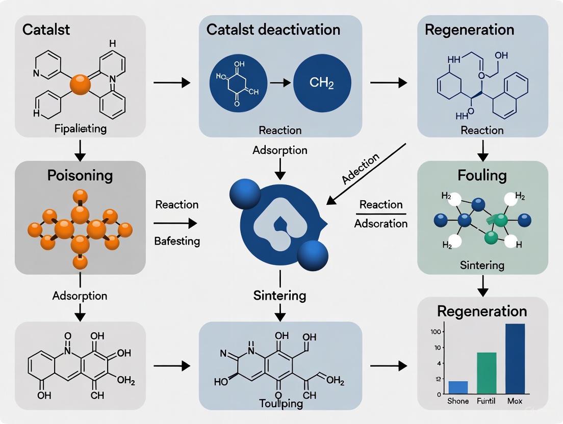
The following diagram illustrates the primary deactivation mechanisms and their direct impacts on the catalyst structure.
Diagram 1: Primary catalyst deactivation mechanisms and their direct effects.
Table 1: Comparative Analysis of Catalyst Deactivation Mechanisms
| Mechanism | Primary Cause | Key Characteristics | Industrially Relevant Examples |
|---|---|---|---|
| Poisoning | Strong chemisorption of impurities on active sites [2] [8]. | Often specific to catalyst/poison pair; can be reversible or irreversible [5] [2]. | S poisoning of Ni reforming catalysts [2]; K poisoning of Pt/TiO₂ in biomass pyrolysis [5]. |
| Coking/Fouling | Deposition of carbonaceous species from reaction stream [1] [3]. | Can block sites and pores; often reversible via combustion [3]; prevalent in hydrocarbon processing [4]. | Coke formation in FCC catalysts [3] [6]; carbon deposition in FTS [1]. |
| Sintering | Exposure to high temperature (and water vapor) [1] [8]. | Irreversible loss of active surface area; agglomeration of metal particles [2] [4]. | Sintering of Co and Fe particles in Fischer-Tropsch Synthesis [1]. |
| Attrition/Crushing | Mechanical stress (collisions, bed weight, thermal stress) [2] [8]. | Physical breakdown of catalyst particles; increased pressure drop; catalyst loss [1] [8]. | Attrition in fluidized-bed Fischer-Tropsch reactors [1]. |
Experimental Methodologies for Investigating Deactivation
A methodical approach combining activity testing with advanced characterization is essential to identify the root cause of deactivation [8]. The following workflow outlines a standard investigative protocol.
Diagram 2: Root cause analysis workflow for catalyst deactivation.
Core Activity and Deactivation Kinetics Measurement
The foundation of deactivation studies is the measurement of catalyst activity as a function of time-on-stream (TOS). Experiments are conducted in laboratory-scale reactors (e.g., fixed-bed, slurry-bed) under controlled conditions mimicking industrial operation [6]. The data collected is used to fit deactivation models.
- Time-on-Stream (TOS) Models: Empirical models correlate activity directly with time. The simplest is the power-law model: ( a(t) = A \cdot t^{n} ), where ( A ) and ( n ) are constants [6]. Another common form is the exponential model: ( a(t) = e^{-kd \cdot t} ), where ( kd ) is the deactivation rate constant [6].
- Coke-Dependent Models: For coking catalysts, activity is often linked to coke content ( Cc ), e.g., ( a(t) = \frac{1}{(1 + \alpha \cdot Cc)^{m}} ) [6].
Essential Characterization Techniques
A suite of characterization techniques is employed to probe the physical and chemical changes in the deactivated catalyst.
Table 2: Key Characterization Techniques for Catalyst Deactivation Analysis
| Technique | Acronym | Primary Function in Deactivation Analysis | Key Measurable Parameters |
|---|---|---|---|
| N₂ Physisorption | BET | Quantifies textural changes [8]. | Surface area, pore volume, pore size distribution. Loss indicates sintering/fouling [8]. |
| X-Ray Fluorescence | XRF | Identifies and quantifies elemental composition of bulk impurities [8]. | Concentration of poisons (S, P, K, heavy metals) on the catalyst [8]. |
| X-Ray Photoelectron Spectroscopy | XPS | Determines elemental composition and chemical state at the surface [4] [8]. | Surface concentration of poisons, oxidation states of active metals, presence of coke. |
| Temperature-Programmed Desorption/Reduction/Oxidation | TPD/TPR/TPO | Probes surface properties and reactivity [8]. | TPD: Active site strength and density. TPO: Nature and quantity of coke deposits [3]. |
| Thermogravimetric Analysis | TGA | Measures weight changes as a function of temperature [4]. | Quantifies coke burn-off (in air/O₂) or metal reduction (in H₂). |
| Transmission Electron Microscopy | TEM/STEM | Provides direct imaging of catalyst nanostructure [4]. | Metal particle size distribution (sintering), location of coke, and mapping of elements. |
| X-Ray Diffraction | XRD | Assesses crystallographic structure [4]. | Crystallite size (sintering), phase changes (e.g., oxidation, carbide formation). |
The Scientist's Toolkit: Key Research Reagents and Materials
- High-Purity Gases (H₂, O₂, He, N₂): Used as reactants, purge gases, and analysis carriers in TPD/TPR/TPO experiments to avoid introducing contaminants [8].
- Model Poison Compounds (e.g., Thiophene, PH₃): Well-defined chemicals used in controlled dosing experiments to simulate feedstock impurities and study poisoning mechanisms [2].
- Calibration Standards for Elemental Analysis (XRF, XPS): Certified reference materials essential for accurate quantification of elemental composition in fresh and spent catalysts [8].
- Oxidizing Agents (e.g., O₂, O₃, NO₂): Used in TPO and regeneration studies to selectively remove coke deposits from catalyst surfaces [3].
- Catalyst Supports (e.g., Al₂O₃, SiO₂, TiO₂, Zeolites): High-surface-area materials that act as scaffolds for active metal phases; their acidity, porosity, and metal-support interactions critically influence deactivation resistance [1] [5].
Foundational Mitigation and Regeneration Strategies
Addressing catalyst deactivation requires a holistic strategy encompassing catalyst design, process engineering, and regeneration protocols.
- Catalyst Design and Selection: Designing catalysts with inherent resistance is the first line of defense. This includes using supports with strong metal-support interactions to inhibit sintering [4], tailoring pore architectures to reduce coke formation and pore blockage [1], and incorporating guard components that sacrificially adsorb poisons [2] [8].
- Process Condition Optimization: Careful control of operating parameters can significantly extend catalyst life. This involves:
- Feedstock Purification: Using guard beds (e.g., ZnO for sulfur removal) or catalytic pretreatments to reduce poison levels in the feed [2].
- Temperature Management: Operating at the lowest feasible temperature to minimize sintering and coking rates. Using dilution or multi-stage reactors can manage exotherms [8].
- Optimized Feed Composition: Adjusting ratios like H₂/CO in Fischer-Tropsch or steam/hydrocarbon in reforming to thermodynamically suppress coking [1].
- Regeneration Techniques: When deactivation occurs, regeneration is key.
- Oxidative Regeneration: The most common method for coke removal, involving controlled combustion with air or O₂. The major challenge is managing exotherms to prevent thermal damage [3].
- Chemical Treatment: Washing with solvents or complexing agents to remove specific poisons (e.g., water washing to remove potassium) [5].
- Reductive Regeneration: Treatment with H₂ at high temperature to remove sulfur poisons (for some catalysts) or reduce oxidized active phases [3] [2].
Catalyst deactivation is an inescapable challenge that fundamentally impacts the efficiency, economics, and sustainability of industrial chemical processes. A deep understanding of its core mechanisms—poisoning, coking, sintering, and attrition—provides the essential framework for diagnosing and combating this phenomenon. Through a rigorous, methodology-driven approach that integrates kinetic modeling with advanced characterization, researchers can pinpoint root causes. This knowledge, in turn, enables the rational design of more robust catalysts and the development of optimized processes and regeneration protocols. As industrial catalysis increasingly pivots to meet the demands of a sustainable economy, including the processing of complex biomass-derived feeds and CO₂ utilization, the principles governing catalyst deactivation and stability will only grow in importance, forming a critical pillar of catalysis research for years to come.
Catalyst deactivation, the loss of activity and/or selectivity over time, is a fundamental challenge that impacts the economic and operational viability of industrial catalytic processes. The development of mitigation and regeneration strategies hinges on a systematic understanding of the underlying decay mechanisms. Within the broader context of catalyst deactivation and regeneration research, this whitepaper provides a structured classification of the six intrinsic mechanisms of catalyst decay. By integrating contemporary research and established industrial knowledge, this guide serves as a technical resource for researchers and scientists aiming to design more robust and durable catalytic systems.
The imperative for such a classification is underscored by the significant costs associated with catalyst replacement and process shutdowns, which can total billions of dollars annually [2]. The time scales of deactivation vary dramatically, from seconds for fluid catalytic cracking catalysts to over a decade for catalysts used in ammonia synthesis, yet decay remains an inevitable process [2]. A precise understanding of these mechanisms is the first step in delaying the inevitable and enhancing catalytic longevity, which is a central thesis in sustainable process design.
A Systematic Classification of Decay Mechanisms
Catalyst deactivation mechanisms can be systematically categorized into six primary intrinsic pathways. These are distinct yet can occur simultaneously or synergistically during operation, leading to a complex interplay that accelerates activity loss. The table below summarizes these core mechanisms, their fundamental causes, and representative chemical processes where they are prevalent.
Table 1: The Six Intrinsic Mechanisms of Catalyst Decay
| Mechanism | Fundamental Cause | Representative Industrial Process |
|---|---|---|
| 1. Poisoning | Strong chemisorption of impurities onto active sites, blocking reactant access. | Ammonia Synthesis, Steam Reforming [2] |
| 2. Coking & Fouling | Physical deposition of carbonaceous species (coke) or other inert materials on active sites and pores. | Fluid Catalytic Cracking, Biomass/Biomass and Solid Waste Gasification [3] [9] |
| 3. Thermal Degradation (Sintering) | Thermally-induced loss of active surface area via crystal growth (Ostwald ripening) or particle migration. | Steam Reforming, Exhaust Gas Treatment [2] |
| 4. Vapor Compound Formation & Transport | Formation of volatile chemical compounds that remove the active phase from the catalyst. | Methanation (via Metal Carbonyls) [2] |
| 5. Mechanical Damage | Physical loss of catalyst integrity through crushing, attrition, or erosion. | Processes with High Fluid Velocity or Pressure Drops [2] |
| 6. Chemical & Phase Transformation | Solid-state reactions leading to undesirable phase changes or loss of critical structural properties. | High-Temperature Oxidation/Reduction Catalysis [10] |
Detailed Mechanism Analysis and Experimental Protocols
Poisoning
Poisoning occurs when a chemical impurity in the feed stream strongly and preferentially chemisorbs onto the catalyst's active sites, rendering them inaccessible for the intended reaction. The strength of this interaction is often electronic, involving the d-orbitals of transition metal catalysts [2].
- Key Poisons: For metal catalysts, poisons are typically classified into nonmetallic ions (e.g., H₂S, PH₃, AsH₃), certain metal ions (e.g., Hg²⁺, Pb²⁺, Cu²⁺), and unsaturated molecules that adsorb irreversibly (e.g., CO) [2].
- Experimental Protocol for Poisoning Study:
- Catalyst Testing: Conduct a catalytic reaction (e.g., steam reforming) in a fixed-bed reactor with a carefully controlled feed containing a trace, quantified amount of the suspected poison (e.g., H₂S).
- Activity Monitoring: Measure the reaction rate constant or conversion as a function of time-on-stream and compare it to a baseline test with a pure feed.
- Post-Reaction Characterization:
- X-ray Photoelectron Spectroscopy (XPS): Used to identify the chemical state of the poison on the catalyst surface (e.g., confirming sulfide species on a poisoned Ni catalyst) [11].
- Temperature-Programmed Desorption (TPD): Can determine the binding strength of the poison to the active sites by measuring the temperature required for its desorption.
- Regeneration Test: Assess reversibility by treating the poisoned catalyst with a regenerant (e.g., hydrogen at elevated temperature) and re-evaluating its activity.
Coking and Fouling
Coke deposition is the most common form of deactivation in processes involving organic compounds, such as in petrochemicals and biomass conversion [3] [9] [2]. It involves the formation of carbonaceous deposits that physically block active sites and pores.
- Coke Classification: Coke can be categorized as (i) encapsulating carbon, which coats metal particles; (ii) filamentous carbon, which grows as carbon nanotubes/nanofibers, potentially disrupting the physical catalyst structure; and (iii) pyrolytic carbon, formed at high temperatures via direct cracking [9].
- Experimental Protocol for Coking Analysis:
- Accelerated Coking Experiment: Perform the target reaction (e.g., toluene steam reforming) under conditions known to promote coking, such as lower steam-to-carbon ratios [9].
- Thermogravimetric Analysis (TGA): The coked catalyst is subjected to TGA in an air atmosphere. The mass loss profile during temperature ramping quantifies the amount of coke and can provide information on its reactivity/burn-off temperature [9].
- Electron Microscopy (SEM/TEM): Used to visualize the morphology of the coke, distinguishing between encapsulating layers and filamentous structures [9].
- Spectroscopic Characterization: Raman spectroscopy can determine the graphitic degree of the carbon deposits, which relates to their stability and difficulty of removal.
Thermal Degradation (Sintering)
Sintering is the thermodynamically driven growth of small catalyst particles or crystallites into larger ones, resulting in a decrease in active surface area. This process becomes significant at temperatures above the Tammann temperature of the active phase [9].
- Mechanisms: Sintering proceeds via two primary pathways: (i) Particle Migration and Coalescence, where entire crystallites migrate and fuse upon contact; and (ii) Ostwald Ripening, where atomic or molecular species detach from smaller particles and diffuse to larger ones [9].
- Experimental Protocol for Sintering Assessment:
- Accelerated Aging: Subject the fresh catalyst to a high-temperature treatment (e.g., in air or inert atmosphere) for a set duration.
- Surface Area Measurement: Use Physisorption (BET method) to track the reduction in total surface area.
- Crystallite Size Analysis: Employ X-ray Diffraction (XRD) to measure the average crystallite size of the active metal (e.g., Ni) using the Scherrer equation. An increase in size indicates sintering.
- Direct Imaging: Transmission Electron Microscopy (TEM) provides direct visual evidence of particle growth and can help distinguish between the two sintering mechanisms.
The following diagram illustrates the logical relationships and experimental characterization pathways for the primary deactivation mechanisms.
Diagram 1: Deactivation mechanisms and characterization techniques.
Vapor Compound Formation and Transport
This mechanism involves the chemical reaction of the active catalytic phase to form a volatile compound that is subsequently removed from the catalyst body by the gas flow. A classic example is the formation of volatile nickel carbonyl (Ni(CO)₄) in methanation reactors operating at low temperatures in the presence of CO, which leads to the physical loss of the active nickel metal [2].
- Experimental Protocol:
- Long-Term Stability Testing: Run the catalyst under simulated industrial conditions, including temperature and pressure cycles.
- Analysis of Effluent Stream: Use sensitive analytical techniques like Gas Chromatography-Mass Spectrometry (GC-MS) or Inductively Coupled Plasma (ICP) analysis of trapped effluent to detect and quantify the vaporized metal species.
- Post-Run Catalyst Analysis: Atomic Absorption Spectrophotometry (AAS) or ICP analysis of the spent catalyst can reveal a measurable loss of the active metal from the catalyst bed [11].
Mechanical Damage
Mechanical failure manifests as catalyst crushing (loss of mechanical strength), attrition (wearing down of particles), or erosion. This leads to an increased pressure drop across a fixed-bed reactor or loss of catalyst from a fluidized bed [2].
- Experimental Protocol:
- Crush Strength Testing: Measure the force required to crush a fresh catalyst pellet using a mechanical press. This establishes a baseline.
- Accelerated Attrition Testing: Subject catalyst particles to a high-velocity gas stream or mechanical stirring in a standardized test apparatus (e.g., a jet-cup attrition tester).
- Post-Test Analysis: Sieve the catalyst after testing to determine the percentage of fines generated. Compare the crush strength of aged catalyst pellets to fresh ones.
Chemical and Phase Transformation
This encompasses solid-state reactions or reconstructions that alter the catalyst's active or supportive phase. For example, in catalytic oxidation, metastable phases engineered for high activity may transform into more stable, less active crystalline structures under operational conditions [10]. Recent research on two-dimensional LaNiO₃ perovskites highlights how microwave shock can be used to create unconventional cubic phases for superior urea oxidation activity, implying that reversion to stable phases is a potential deactivation route [10].
- Experimental Protocol:
- In Situ/Operando Characterization: Use in situ X-ray Diffraction (XRD) or XPS to monitor the catalyst's crystal structure and surface chemistry in real-time under reaction conditions.
- Stability Testing: Expose the catalyst to prolonged reaction conditions or thermal treatments.
- Post-Reaction Analysis: Compare the XRD patterns and XPS spectra of the spent catalyst with the fresh material to identify new, stable, but inactive phases that have formed.
The Scientist's Toolkit: Research Reagent Solutions
The following table details key reagents, materials, and characterization tools essential for studying catalyst deactivation, as derived from the featured research.
Table 2: Essential Research Reagents and Materials for Deactivation Studies
| Tool/Reagent | Function & Application in Deactivation Research |
|---|---|
| Transition Metal Precursors (e.g., Co(NO₃)₂·6H₂O [12]) | Source of active metal for catalyst synthesis, used in precipitation methods to create model catalysts for deactivation studies. |
| Precious Metal Catalysts (e.g., Rh, Pt [9]) | High-activity, often more coke-resistant catalysts; used as benchmarks to understand deactivation mechanisms in severe conditions. |
| MXene (Ti₃C₂Tₓ) [10] | A two-dimensional conductive support material; studied for its role in enhancing stability and mitigating coke formation in fiber-based sensors and catalysts. |
| Zeolites (e.g., ZSM-5) [3] | Microporous aluminosilicate catalysts/supports; model systems for studying deactivation by coking and regeneration via oxidation with O₂ or O₃. |
| Thermogravimetric Analyzer (TGA) [9] | A key instrument for quantifying the amount of coke deposited on a catalyst by measuring mass loss during controlled combustion. |
| X-ray Photoelectron Spectrometer (XPS) [11] | Surface-sensitive technique used to identify the chemical states of elements on the catalyst surface, crucial for detecting poisons (e.g., sulfides) and oxidation states. |
| Inductively Coupled Plasma (ICP) Spectrometer [11] | An analytical technique for detecting trace levels of metals, used to confirm metal loss from catalysts via vapor transport mechanisms. |
Quantitative Data on Deactivation and Regeneration
The economic and operational impact of deactivation necessitates quantitative data for lifecycle analysis and process optimization. The following table consolidates key metrics related to catalyst decay and recovery.
Table 3: Quantitative Metrics in Catalyst Deactivation and Regeneration
| Metric | Data / Value | Context & Significance |
|---|---|---|
| Catalyst Lifespan (Ammonia Synthesis) | 5–10 years [2] | Illustrates the potential for long-term stability in well-controlled, thermodynamically favorable processes. |
| Catalyst Lifespan (Steam Reforming) | 5–6 years (modern catalysts) [2] | Highlights improvements in catalyst design (e.g., coke resistance, mechanical strength) that have extended operational life. |
| Capacitance Retention (Stable Catalyst) | 97.35% after 10,000 cycles [10] | A measure of stability in functional materials (e.g., for flexible energy storage), indicating excellent resistance to mechanical and electrochemical degradation. |
| Regeneration Efficiency (Ozone vs. Air) | Effective at lower temperatures [3] | Advanced regeneration methods like ozone treatment can remove coke more efficiently and with less thermal damage to the catalyst than conventional air combustion. |
| Sintering Onset | Above Tammann Temperature [9] | The Tammann temperature (approx. 0.5 × melting point in Kelvin) is a critical threshold for the onset of significant thermal sintering. |
| Industry Cost of Deactivation | Billions of USD/year [2] | underscores the massive economic driver behind fundamental and applied research into deactivation mechanisms and regeneration technologies. |
The systematic classification of catalyst decay into six intrinsic mechanisms—poisoning, coking, thermal degradation, vapor transport, mechanical damage, and chemical transformation—provides a foundational framework for both academic research and industrial practice. As catalytic processes become increasingly critical for a sustainable chemical industry, energy conversion, and environmental protection, a deep understanding of these deactivation pathways is more vital than ever. Current research frontiers, including the use of microwave thermal engineering to stabilize unconventional phases [10] and machine learning to predict catalyst lifetime [13] [12], are poised to transform our ability to design catalysts that are not only highly active but also intrinsically resistant to decay. The continued refinement of this systematic understanding, integrated with advanced materials design and intelligent process control, will form the cornerstone of next-generation catalytic technologies with extended service life and enhanced economic and environmental performance.
Catalyst deactivation is a critical challenge that impacts the economic viability and operational stability of industrial chemical processes, including those in pharmaceutical development [14]. Among the various deactivation pathways, poisoning and inactivation via chemical reactions represent some of the most chemically complex and detrimental mechanisms. These processes involve the irreversible or strongly reversible chemical interaction of contaminants with active sites, leading to permanent activity loss [8]. Within the broader thesis of catalyst deactivation and regeneration research, understanding these molecular-level chemical interactions is paramount for developing poisoning-resistant catalysts and extending catalytic lifetime in drug synthesis and other fine chemical productions [5]. This technical guide provides an in-depth examination of the fundamental chemical mechanisms, experimental characterization methodologies, and computational modeling approaches relevant to researcher and scientist workflows in catalytic reaction engineering.
Fundamental Chemical Mechanisms of Catalyst Poisoning
Catalyst poisoning occurs when impurities present in reactant streams form strong chemical bonds with active sites, rendering them inaccessible for the intended catalytic reaction [14] [8]. The strength and nature of these chemical interactions determine whether poisoning is reversible or irreversible under process conditions.
Molecular-Level Interaction Mechanisms
Chemisorption Blocking: Poisoning molecules competitively and strongly adsorb to active sites, physically blocking reactant access. Unlike reversible inhibition, poisoning involves strong covalent or ionic bonding that cannot be reversed simply by removing the poison from the feed stream [14]. The effectiveness of a poison depends on its electron density, molecular geometry, and strength of surface complex formation.
Electronic Structure Modification: Certain poisons alter the electronic properties of catalytic sites through ligand effects. For example, electronegative elements like chlorine or sulfur can withdraw electron density from metal centers, modifying their adsorption properties and reducing their ability to activate reactants [8].
Selective Site Poisoning: In multifunctional catalysts, poisons may selectively target specific site types. Research on Pt/TiO₂ catalysts used in catalytic fast pyrolysis demonstrated that potassium preferentially poisons Lewis acid Ti sites both on the support and at the metal-support interface, while metallic Pt clusters remain largely uncontaminated [5].
Chemical Compound Formation: Some poisons react with active components to form new, inactive chemical compounds. For instance, vanadium species in heavy feeds can react with catalyst supports to form low-melting-point vanadates that destroy pore structure and active sites [15].
Common Catalytic Poisons and Their Origins
Table 1: Common Catalyst Poisons and Their Chemical Sources
| Poison Category | Specific Poisons | Typical Sources | Primary Mechanisms |
|---|---|---|---|
| Metallic Poisons | Mercury, Lead, Arsenic | Contaminated feedstocks, impurities | Amalgamation, strong chemisorption, site blocking [8] |
| Non-Metallic Poisons | Sulfur, Chlorine, Silicon | Feed impurities, process additives | Strong covalent bonding, electronic effects [8] |
| Alkali & Alkaline Earth Metals | Potassium, Sodium | Biomass feedstocks, contaminants | Neutralization of acid sites, site blocking [5] |
| Heavy Metals | Vanadium, Nickel | Heavy petroleum fractions, residues | Pore blockage, compound formation, site destruction [15] |
Experimental Methodologies for Poisoning Mechanism Analysis
Understanding poisoning mechanisms requires sophisticated characterization techniques that can identify the chemical state and spatial distribution of poisons on catalyst surfaces.
Catalyst Characterization Techniques
Surface Spectroscopy Methods: X-ray photoelectron spectroscopy (XPS) provides information about the chemical state and composition of the top 1-10 nm of catalyst surfaces, enabling identification of poison oxidation states and bonding environments [8]. This technique can distinguish between different sulfur species (sulfide, sulfate) or determine whether potassium is present as metallic, oxide, or hydroxide forms.
Temperature-Programmed Techniques: Temperature-programmed desorption (TPD) measures the strength of adsorption between poisons and catalyst surfaces by monitoring desorption as a function of temperature [8]. Stronger poison-catalyst interactions result in higher desorption temperatures, providing insights into reversibility and binding energy.
Elemental Analysis Methods: X-ray fluorescence (XRF) and proton-induced X-ray emission (PIXE) provide quantitative analysis of poison elements deposited on catalyst surfaces, even at trace concentrations [8]. These techniques are particularly valuable for mapping poison distribution across catalyst particles.
Surface Area and Porosity Analysis: BET surface area analysis measures reductions in accessible surface area resulting from poison deposition, helping distinguish between uniform monolayer coverage and pore blockage mechanisms [8].
Accelerated Deactivation Testing Protocols
Industrial catalyst lifetimes often extend to years, making real-time deactivation studies impractical. Accelerated deactivation methodologies subject catalysts to extreme conditions or highly contaminated feeds to simulate long-term poisoning in condensed timeframes [15].
High-Severity Testing: Exposure to elevated temperatures accelerates thermodynamic processes like sintering and can promote poison-catalyst interactions. However, excessively high temperatures may introduce deactivation mechanisms not representative of actual operating conditions [15].
Concentrated Poison Exposure: Using feeds artificially enriched with potential poisons (e.g., potassium-doped biomass, sulfur-spiked hydrocarbons) accelerates poisoning while maintaining chemical relevance. This approach successfully predicted potassium poisoning in Pt/TiO₂ catalysts for biomass conversion [5].
Protocol Validation: Accelerated methods must be validated against industrially deactivated catalysts to ensure they reproduce the same chemical states, spatial distributions, and structural changes observed in practice [15].
Quantitative Modeling of Catalyst Deactivation Kinetics
Mathematical modeling of deactivation kinetics is essential for predicting catalyst lifetime and optimizing regeneration strategies. Deactivation models generally correlate catalyst activity with time-on-stream, poison concentration, or operating conditions [6].
Fundamental Deactivation Rate Equations
The activity of a catalyst at any time ( t ) is defined as the ratio of its current reaction rate to its initial rate:
[ a(t) = \frac{r(t)}{r(t=0)} ]
The rate of deactivation is typically expressed as a power-law function:
[ -\frac{da}{dt} = k_d \cdot a^n ]
where ( k_d ) is the deactivation rate constant and ( n ) is the order of deactivation [6].
Classification of Deactivation Kinetic Models
Table 2: Mathematical Models for Catalyst Deactivation Kinetics
| Model Type | Mathematical Form | Applicability | Key Parameters |
|---|---|---|---|
| Time-Based Models | ( a(t) = A \cdot t^n ) [6] | Fluid catalytic cracking, rapid deactivation systems | A, n (empirical constants) |
| Exponential Decay Models | ( a(t) = e^{-k_d \cdot t} ) [6] | Hydrotreating, hydrocarbon processing | kd (deactivation rate constant) |
| Generalized Power Law with Residual Activity | ( a(t) = a{\infty} + (1 - a{\infty}) \cdot e^{-k_d \cdot t} ) [6] | Fischer-Tropsch, systems with stable residual activity | kd, a∞ (residual activity) |
| Selective Deactivation Models | ( ai(t) = f(Cj, t) ) for component i [6] | Multi-component reaction systems | Component-specific rate constants |
Mitigation Strategies for Catalyst Poisoning
Process-Based Mitigation Approaches
Feedstock Purification: Implementing guard beds, adsorbents, or pretreatment stages to remove potential poisons before they contact the primary catalyst. For example, chloride guards can protect sensitive catalysts in pharmaceutical processes [8].
Operational Modifications: Adjusting temperature, pressure, or space velocity to minimize poison adsorption while maintaining target conversion levels. In some cases, dilution air can moderate temperatures and reduce poisoning rates [8].
Catalyst Formulation Design: Developing catalysts with increased poison tolerance through promoters or modifiers that block poison adsorption sites while maintaining activity for target reactions [5].
Regeneration of Poisoned Catalysts
Chemical Washing: Water washing successfully reversed potassium poisoning on Pt/TiO₂ catalysts by dissolving and removing potassium deposits [5]. Acid or base washes may be employed for other poison types.
Oxidative Regeneration: Burning carbonaceous deposits can restore activity when poisons are associated with coke layers, though this approach is ineffective for metallic poisons strongly bonded to catalyst surfaces [14].
Research Reagent Solutions for Poisoning Studies
Table 3: Essential Research Reagents for Catalyst Poisoning Investigations
| Reagent/Material | Function in Research | Application Context |
|---|---|---|
| Model Poison Compounds | Controlled introduction of specific poisoning elements | Potassium salts for biomass catalyst studies, thiophenes for sulfur poisoning [5] |
| Standard Reference Catalysts | Baseline for deactivation comparison | Pt/TiO₂ for acid site poisoning studies, CoMo/γ-Al₂O₃ for hydrotreating [5] [15] |
| Surface Characterization Standards | Calibration of analytical equipment | XPS reference samples with known surface concentrations [8] |
| Guard Bed Adsorbents | Poison removal studies | Zinc oxide for sulfur removal, alumina for chloride capture [8] |
| Regeneration Reagents | Reactivation of poisoned catalysts | Dilute acids for metal removal, oxidative solutions for carbon removal [5] |
Visualizing Catalyst Poisoning Mechanisms and Experimental Workflows
Figure 1: Chemical Poisoning Mechanism and Investigation Workflow
Figure 2: Accelerated Deactivation Study Protocol
Catalyst deactivation presents a fundamental challenge in industrial catalysis, compromising process efficiency, sustainability, and economic viability. Among various deactivation pathways, mechanical mechanisms—including fouling, coking, and attrition—represent predominant causes of activity loss across numerous chemical processes. These phenomena occur through physical deposition or structural degradation that blocks active sites or compromises catalyst integrity. Within the broader context of catalyst deactivation and regeneration research, understanding these mechanical mechanisms is crucial for developing robust catalytic systems and effective regeneration protocols. This whitepaper provides a comprehensive technical examination of fouling, coking, and attrition, integrating recent scientific advancements with practical methodologies for researchers and drug development professionals engaged in catalyst design and optimization.
Fundamental Mechanisms of Catalyst Deactivation
Catalyst deactivation encompasses multiple pathways that can be broadly categorized as chemical, thermal, or mechanical in nature. Figure 1 illustrates the primary relationships between these deactivation mechanisms.
Figure 1. Catalyst Deactivation Mechanisms. This diagram categorizes the primary pathways leading to catalyst activity loss, highlighting the position of mechanical mechanisms within the broader deactivation landscape.
While thermal degradation and poisoning are typically slow and often irreversible processes, mechanical deactivation via fouling and coking can occur rapidly but is frequently reversible through appropriate regeneration protocols [6]. The timescale for deactivation varies significantly across processes, from seconds in fluidized catalytic cracking (FCC) to several years in ammonia synthesis [3] [16].
Mechanical Deactivation Pathways
Coking
Coking represents a predominant mechanical deactivation mechanism in processes involving organic compounds and heterogeneous catalysts, particularly in petrochemical operations and biomass conversion [3] [17].
Formation Mechanisms
Coke formation proceeds through three well-established stages: (1) hydrogen transfer at acidic sites, (2) dehydrogenation of adsorbed hydrocarbons, and (3) gas-phase polycondensation [3] [16]. The specific type of coke generated depends on both catalyst characteristics and reaction parameters, with formation rates influenced by temperature, pressure, and feedstock composition.
Coke affects catalyst performance through two primary pathways: active site poisoning via overcoating of catalytic centers and pore blockage that renders active sites inaccessible to reactants [3] [16]. The morphological properties of coke deposits—including their location, composition, and structure—significantly influence regeneration strategies and potential for activity recovery.
Industrial Context: Fluid Catalytic Cracking
In fluid catalytic cracking (FCC) units, coke formation occurs rapidly during the cracking of hydrocarbon feeds at elevated temperatures (approximately 900°F, 482°C) [18]. The coke coats the catalyst surface, preventing access to active sites and necessitating continuous regeneration. FCC designs typically incorporate dedicated regeneration chambers where coke is burned from the catalyst surface with air before the reactivated catalyst returns to the reaction zone [18]. This continuous regeneration cycle is essential for maintaining catalytic activity in rapid coking environments.
Fouling
Fouling encompasses the physical deposition of foreign materials—such as inorganic scales, corrosion products, catalyst fines, and miscellaneous debris—on catalyst surfaces or within reactor components.
Fouling Manifestations in Industrial Systems
In catalytic cracking units, operational deposits typically comprise mixtures of organic and inorganic materials including iron, sulfates, and sulfides [18]. These deposits range in consistency from hard, coke-like materials to sludge-like substances. Common fouling locations include heat exchanger bundles in cycle oil lines, feed stream pre-heat furnaces, and fractionation columns [18].
The presence of unsaturated compounds (alkenes) formed during catalytic reactions can lead to deposition of low-molecular weight polymers and varnish within fractionators and associated heat exchange equipment [18]. Additionally, specialized vessels such as slurry settler tanks accumulate catalyst fines suspended in slurry oil, forming concrete-like solids impregnated with hydrocarbons that constitute hazardous waste [18].
Attrition
Attrition involves the physical breakdown of catalyst particles due to mechanical stresses encountered during reactor loading, operation, and regeneration cycles. This phenomenon is particularly prevalent in fluidized bed and moving bed reactor systems where particle-to-particle and particle-to-reactor wall contacts generate continuous abrasive forces.
While the search results provide limited specific details on attrition mechanisms, this form of mechanical degradation produces fine catalyst particles that can be elutriated from the reactor system, resulting in catalyst inventory loss and potential downstream equipment fouling. Attrition typically manifests through three primary pathways: (1) surface abrasion that gradually reduces particle size, (2) particle fragmentation that generates new fines, and (3) impact failure that causes catastrophic particle fracture.
Quantitative Deactivation Modeling
Mathematical modeling of catalyst deactivation plays a crucial role in process simulation, reactor design, and optimization of industrial catalytic reactors [6]. Deactivation models can be categorized as selective or non-selective based on the mechanism of active site consumption, and as theoretical, empirical, or semi-empirical based on their mathematical derivation.
Table 1: Catalyst Deactivation Models for Mechanical Mechanisms
| Model Type | Mathematical Expression | Application Context | Key Parameters | References |
|---|---|---|---|---|
| Time-Dependent (Power Law) | a(t) = Atⁿ |
Fluidized catalytic cracking (FCC) | A = pre-exponential factor, n = decay order, t = time | [6] |
| Time-Dependent (Exponential) | a(t) = e^(-αt) |
Catalytic pyrolysis of gas oils; Propane dehydrogenation | α = deactivation coefficient, t = time-on-stream | [6] |
| Temperature-Dependent | a = α₀e^(-αt) α = A·exp(-E/RT) |
FCC; Biomass-derived chemicals | α₀ = initial activity, E = activation energy, R = gas constant, T = temperature | [6] |
| Generalized Power Law | -da/dt = k_d·aⁿ a = e^(-k_d t) (n=1) a = 1/(1 + k_d t) (n=2) |
Fischer-Tropsch synthesis; Ethylbenzene dehydrogenation | k_d = deactivation rate constant, n = deactivation order | [6] |
| Coke Content-Based | a(t) = f(C_coke) |
Vacuum gas oil (VGO) cracking | C_coke = coke content on catalyst | [6] |
The choice of an appropriate deactivation model depends on the specific catalyst system, reaction conditions, and dominant deactivation mechanism. For rapid deactivation processes such as FCC, time-dependent models often provide sufficient accuracy, while more complex systems requiring precise activity prediction may necessitate models incorporating temperature, coke content, and reactant concentration dependencies [6].
Experimental Methodologies for Deactivation Analysis
Laboratory-Scale Deactivation Protocols
Figure 2 outlines a generalized experimental workflow for investigating mechanical deactivation mechanisms.
Figure 2. Experimental Workflow for Deactivation Studies. This diagram outlines the systematic approach for investigating mechanical deactivation mechanisms in laboratory settings.
Catalyst Characterization Techniques
Comprehensive catalyst characterization before and after deactivation provides critical insights into mechanical degradation mechanisms:
- Textural Properties: Nitrogen physisorption measurements determine surface area, pore volume, and pore size distribution changes following fouling or coking [17].
- Coke Characterization: Temperature-programmed oxidation (TPO), X-ray photoelectron spectroscopy (XPS), and Raman spectroscopy identify coke quantity, structure, and location [16].
- Mechanical Strength: Attrition resistance testing through ASTM standard methods evaluates particle integrity under simulated operating conditions.
- Morphological Analysis: Scanning electron microscopy (SEM) visualizes surface deposits, pore blockage, and particle fragmentation [17].
Accelerated Deactivation Protocols
Controlled laboratory deactivation studies employ strategic approaches to simulate long-term operational impacts:
- Extended Time-on-Stream: Operating catalysts beyond normal lifespan under standard conditions to observe natural deactivation progression [6].
- Severity Enhancement: Increasing temperature, introducing model foulants, or extending cycle times to accelerate deactivation mechanisms.
- Model Compound Introduction: Adding known coking precursors (e.g., polyaromatics) or foulants (e.g., metalorganic compounds) to feedstock.
The Scientist's Toolkit: Research Reagent Solutions
Table 2: Essential Research Reagents for Deactivation and Regeneration Studies
| Reagent Category | Specific Examples | Function in Deactivation/Regeneration Research | Application Context | |
|---|---|---|---|---|
| Oxidizing Agents | O₂, O₃, NOₓ | Coke combustion; Catalyst regeneration | Oxidation-based regeneration protocols | [3] [16] |
| Gasification Agents | CO₂, H₂O | Coke gasification to syngas; Alternative regeneration | Sustainable regeneration with value recovery | [16] |
| Reducing Agents | H₂, NaBH₄ | Coke hydrocracking; Catalyst reduction | Hydrogenation-based regeneration; Pd catalyst activation | [16] [19] |
| Model Coke Precursors | Polyaromatic compounds; Phenol | Controlled coking studies; Deactivation mechanism elucidation | Laboratory deactivation protocols | [17] |
| Supercritical Fluids | CO₂ (scCO₂) | Coke extraction; Pore cleaning | Supercritical fluid extraction regeneration | [3] [16] |
| Acid-Base Reagents | NH₄OAc; Phosphate buffers | pH control; Reaction medium optimization | Pd-catalyzed deallylation assays | [19] |
Regeneration Strategies for Mechanical Deactivation
Conventional Regeneration Approaches
Oxidation-Based Regeneration
Oxidation represents the most widely applied regeneration method for coke deactivation, typically employing air or oxygen at elevated temperatures:
- Air/O₂ Combustion: Industrial standard for FCC and other petrochemical processes; exothermic nature requires careful temperature control to prevent catalyst damage [16].
- Ozone (O₃) Treatment: Enables low-temperature regeneration; effectively regenerates coked ZSM-5 catalysts while minimizing thermal degradation [3] [16].
- Oxynitride (NOₓ) Applications: Alternative oxidants that can modify combustion pathways and reduce local hot spots.
The exothermic nature of coke combustion presents significant challenges, including localized temperature gradients (hot spots) that can permanently damage catalyst structure through sintering or phase transformation [3] [16]. Sophisticated reactor control strategies are essential for managing these thermal effects during commercial regeneration operations.
Gasification and Hydrogenation
Alternative regenerative approaches focus on chemical conversion rather than combustion of carbonaceous deposits:
- CO₂ Gasification: Converts coke to CO via Boudouard reaction (C + CO₂ → 2CO); produces valuable syngas while reducing CO₂ emissions [16].
- Steam Reforming: Reacts coke with H₂O to generate CO/H₂ mixtures; simultaneously cleans catalyst and produces useful synthesis gas.
- Hydrogen Treatment: Employes H₂ for hydrocracking of carbon deposits; particularly effective for aliphatic coke components [16].
Emerging Regeneration Technologies
Advanced regeneration methodologies continue to evolve, offering improved efficiency and reduced environmental impact:
- Supercritical Fluid Extraction (SFE): Utilizes unique solvent and transport properties of supercritical fluids (e.g., CO₂) to extract coke from porous catalyst matrices at moderate temperatures [3] [16].
- Microwave-Assisted Regeneration (MAR): Applies selective heating mechanisms that can potentially reduce energy consumption and improve coke removal efficiency.
- Plasma-Assisted Regeneration (PAR): Employs non-thermal plasma to activate regeneration reactions at lower temperatures.
- Atomic Layer Deposition (ALD): Techniques that can potentially restore or protect catalyst surfaces during regeneration cycles [3].
Environmental Implications and Sustainability Considerations
Regeneration of catalysts deactivated by mechanical mechanisms carries significant environmental implications that must be addressed within modern sustainability frameworks:
- CO₂ Emissions: Conventional combustion-based regeneration in FCC units alone contributes 40-45% of total CO₂ emissions from refinery operations [16].
- Alternative Approaches: Gasification-based regeneration methods transform coke into synthesis gas (CO + H₂), simultaneously restoring catalyst activity and producing valuable chemical feedstocks [16].
- Waste Minimization: Advanced extraction technologies enable conversion of hazardous waste materials (e.g., K-coded catalyst fines) to non-hazardous status through constituent removal, significantly reducing disposal challenges [18].
Life cycle assessment (LCA) and techno-economic analysis (TEA) methodologies provide critical frameworks for evaluating the environmental footprint and economic viability of regeneration strategies, particularly when comparing conventional and emerging technologies [17].
Mechanical deactivation through fouling, coking, and attrition remains an inevitable challenge in industrial catalytic processes, particularly in petrochemical operations and emerging biomass conversion technologies. A comprehensive understanding of these mechanisms—supported by robust mathematical modeling and advanced characterization techniques—enables the development of effective mitigation and regeneration strategies. The ongoing evolution of regeneration technologies, particularly those emphasizing environmental sustainability and circular economy principles, continues to enhance catalyst longevity and process efficiency. Future research directions should focus on integrated approaches combining advanced materials design with sophisticated process control to minimize deactivation impacts while maximizing catalyst service life within the broader context of sustainable chemical processing.
Catalyst deactivation represents a fundamental challenge in industrial catalysis, directly impacting process efficiency, economic viability, and environmental sustainability. Among various deactivation pathways, thermal mechanisms including sintering and thermal degradation constitute irreversible processes that critically diminish catalyst performance by altering the active phase microstructure and chemical composition [20]. Within the broader context of catalyst deactivation and regeneration research, understanding these thermally-induced phenomena is paramount for developing next-generation catalytic systems with enhanced longevity and stability under demanding operational conditions. This whitepaper provides a comprehensive technical examination of sintering and thermal degradation mechanisms, integrating current scientific understanding with practical methodologies for their investigation and mitigation.
Sintering describes the thermal-induced agglomeration of catalyst nanoparticles, resulting in reduced active surface area, while thermal degradation encompasses broader material transformations including phase changes, solid-state reactions, and support collapse [3] [20]. These processes manifest across diverse catalytic systems—from supported metal catalysts in petroleum refining to ceramic oxide systems in high-temperature applications—imposing significant limitations on catalyst lifetime and regeneration potential [21] [22]. The following sections present a detailed analysis of these mechanisms, supported by experimental data and methodologies relevant to researchers and development professionals engaged in catalyst design and optimization.
Fundamental Mechanisms of Sintering
Sintering represents a primary deactivation pathway for supported metal catalysts, involving the thermally-induced loss of active surface area through crystallite growth and migration. This process occurs via two predominant mechanisms: atomic migration (Ostwald ripening) involving the transport of individual metal atoms, and particle migration with subsequent coalescence [20]. The driving force for both pathways is the reduction of surface free energy, with kinetics strongly dependent on temperature, atmosphere, and metal-support interactions.
The microstructural evolution during sintering directly impacts catalytic performance metrics. Research on circular Al honeycombs demonstrates that elevated sintering temperatures (400–600°C) enhance metallurgical bonding but simultaneously promote elemental diffusion phenomena that alter local mechanical properties [21]. In supported catalyst systems, sintering progresses through distinct stages: initial rapid surface atom migration, followed by particle coalescence and eventual stabilization of larger, thermodynamically favored crystallites with diminished surface-to-volume ratios.
Table 1: Sintering Mechanisms and Characteristics
| Mechanism | Process Description | Temperature Dependence | Key Influencing Factors |
|---|---|---|---|
| Atomic Migration (Ostwald Ripening) | Migration of individual atoms from smaller to larger particles | High, typically >0.3-0.5 Tmelt | Metal volatility, surface diffusivity, interfacial energy |
| Particle Migration & Coalescence | Movement and collision of entire crystallites | Moderate, >0.2 Tmelt | Metal-support interaction strength, particle size/mobility |
| Phase Transformation | Solid-state reactions and new phase formation | Variable, dependent on specific system | Chemical composition, atmosphere, support reactivity |
Thermal Degradation Pathways
Thermal degradation encompasses a spectrum of material transformations beyond simple particle growth, including phase segregation, support collapse, and chemical composition changes that collectively degrade catalytic function. In ceramic catalyst systems such as Al2O3/ZrO2 composites, thermal degradation manifests as accelerated grain growth, pore coarsening, and phase transformations that compromise mechanical integrity and active site accessibility [22].
The degradation of polyamide 12 (PA12) powder in selective laser sintering processes illustrates the complex interplay of thermal and oxidative pathways, where successive thermal cycles induce chain scission, cross-linking, and evaporation of low molecular weight components [23]. These chemical changes alter powder flowability, crystallinity, and ultimately the mechanical performance of fabricated parts—phenomena with direct parallels to catalyst thermal degradation.
Beyond structural changes, thermal degradation induces performance-impairing transformations including:
- Loss of structural promoters that stabilize active phases
- Collapse of porous networks essential for reactant access
- Solid-state reactions between active components and supports
- Vapor formation and transport of active species
Table 2: Thermal Degradation Manifestations in Different Catalyst Systems
| Catalyst System | Primary Thermal Degradation Modes | Critical Temperature Range | Performance Consequences |
|---|---|---|---|
| Supported Metals (Pt, Pd, Ni) | Metal support compound formation, pore collapse | 400-800°C | Active surface area loss, diffusion limitations |
| Metal Oxide Ceramics (Al2O3/ZrO2) | Polymorphic transformations, exaggerated grain growth | >1000°C | Mechanical failure, surface area reduction |
| Zeolites | Dealumination, framework collapse | >600°C | Acid site loss, structural degradation |
| Polymer-Based Systems (PA12) | Chain scission, cross-linking, oxidation | 140-200°C | Mechanical property deterioration, flowability reduction |
Experimental Methodologies for Investigation
Thermal Analysis Protocols
Thermogravimetric Analysis (TGA) provides quantitative data on thermal stability and decomposition profiles. For Al2O3/ZrO2 composites, samples are heated from ambient to 1400°C at 2°C/min in air atmosphere, with mass changes recorded to determine decomposition temperatures and stability thresholds [22]. This methodology identifies organic additive removal temperatures and initial sintering onset.
Differential Scanning Calorimetry (DSC) reveals thermal transitions and energetics of degradation processes. In PA12 powder studies, DSC analysis employs heating rates of 10°C/min under nitrogen purge from 25°C to 220°C, with subsequent cooling and reheating cycles to quantify crystallinity changes and oxidative degradation [23]. The degree of crystallinity is calculated from melting enthalpies relative to 100% crystalline reference materials.
Structural and Microstructural Characterization
X-Ray Diffraction (XRD) identifies phase evolution during thermal treatment. Protocol specifications include: Cu Kα radiation (λ = 1.5406 Å), 40 kV operating voltage, 30 mA current, and 0.02° step size over 10-80° 2θ range [22]. Rietveld refinement quantifies phase fractions and crystallite size using Scherrer equation analysis, detecting transitions such as γ-Al2O3 to α-Al2O3 or tetragonal to monoclinic ZrO2.
Scanning Electron Microscopy (SEM) visualizes microstructural evolution. Samples are prepared by dispersion on conductive carbon tape with gold sputter coating (10-15 nm thickness) to prevent charging [23]. Imaging at 10-15 kV accelerating voltage with secondary electron detection reveals particle morphology, grain growth, and pore structure changes at various sintering stages.
Physical Property Measurements
Dilatometric Analysis determines dimensional changes during sintering. For technical ceramics, measurements employ heating rates of 2-5°C/min to 1400-1600°C in air atmosphere, with sample dimensions precisely recorded to calculate linear shrinkage, sintering rates, and coefficient of thermal expansion [22].
Porosity and Density Analysis combines helium pycnometry (DIN 66137-2) for true density with Archimedes method (ISO 60) for bulk density, enabling calculation of total porosity and pore size distribution changes after thermal treatment [23].
Diagram 1: Experimental workflow for sintering and thermal degradation analysis
Research Reagent Solutions and Essential Materials
Table 3: Essential Materials for Sintering and Thermal Degradation Research
| Material/Reagent | Specification | Research Function | Application Example |
|---|---|---|---|
| Al2O3 Powder | TM-DAR, particle size 0.12 ± 0.3 µm [22] | Ceramic matrix material | High-temperature catalyst support studies |
| ZrO2 Powder | TZ-PX-245, 3% mol Y2O3 stabilized, 0.04 µm [22] | Phase-stabilized ceramic component | Composite catalyst supports investigation |
| Diammonium Hydrogen Citrate (DAC) | Analytical grade, Sigma-Aldrich [22] | Dispersing agent for ceramic slurries | Slip casting preparation of model structures |
| Citric Acid (CA) | Analytical grade, POCH Gliwice/Avantor [22] | Co-dispersant for colloidal processing | pH adjustment and suspension stabilization |
| Polyvinyl Alcohol (PVA) | 10% aqueous solution, Sigma-Aldrich [22] | Binder for green body formation | Providing mechanical strength before sintering |
| PA12 Powder | PA 2200, virgin material [23] | Polymer catalyst model system | Thermal degradation and recycling studies |
| Nitrogen Gas | High purity (99.999%) | Inert atmosphere provision | Oxidative degradation prevention during testing |
Data Presentation and Quantitative Analysis
Quantitative assessment of sintering and thermal degradation provides critical insights for catalyst design and operational parameter optimization. The following tables consolidate experimental data from multiple research studies to establish performance thresholds and degradation kinetics.
Table 4: Sintering Temperature Effects on Material Properties in Al/Mg Systems
| Sintering Temperature (°C) | Phase Composition | Diffusion Depth (µm) | Microhardness (HV) | Plateau Stress (MPa) |
|---|---|---|---|---|
| 400 | Al3Mg2 and Al12Mg17 [21] | Minimal | Baseline | Not reported |
| 450 | Al(Mg) solid solution only [21] | Moderate | Enhanced | Not reported |
| 500 | Al(Mg) solid solution [21] | Significant | Further enhanced | Not reported |
| 600 | Al(Mg) solid solution [21] | Maximum | Maximum | 63.2 |
Table 5: Thermal Degradation Indicators in PA12 Powder During Reuse Cycles
| Reuse Cycle | Crystallinity (%) | Molecular Weight Change | Particle Fracturing | Flowability |
|---|---|---|---|---|
| Virgin | Maximum [23] | Baseline | Minimal | Optimal |
| 2nd | Slight decrease [23] | Moderate increase | Minor | Slight reduction |
| 4th | Noticeable decrease [23] | Significant increase | Apparent | Moderate reduction |
| 6th | Substantial decrease [23] | Maximum observed | Pronounced | Significantly impaired |
| 8th | Minimum [23] | Stabilized at high values | Severe | Poor |
Diagram 2: Interrelationships in thermal degradation pathways
Mitigation Strategies and Regeneration Approaches
Addressing sintering and thermal degradation requires multifaceted strategies encompassing material design, operational parameters, and regeneration protocols. Effective mitigation approaches include:
Stabilization through Structural Promoters: Incorporating thermally stable additives such as Y2O3-stabilized ZrO2 inhibits phase transformations and retards grain growth up to 1400°C [22]. These structural promoters create diffusion barriers that impede atomic migration, thereby preserving surface area and active site distribution under thermal stress.
Advanced Regeneration Techniques: Emerging methods including microwave-assisted regeneration (MAR) and plasma-assisted regeneration (PAR) enable controlled thermal treatment that removes deactivating deposits while minimizing structural damage to the catalyst foundation [3]. These techniques offer superior temperature control compared to conventional thermal regeneration, preventing additional sintering during reactivation cycles.
Operational Parameter Optimization: Strategic control of process conditions—including temperature ramping rates (2-5°C/min optimal for ceramics), atmosphere composition (nitrogen vs. air), and maximum temperature exposure—significantly influences degradation kinetics [22] [23]. Implementation of thermal cycling protocols with controlled cooling phases further mitigates cumulative damage.
The integration of these approaches within a comprehensive catalyst lifecycle management strategy extends functional longevity while maintaining catalytic performance across operational campaigns. Future research directions focus on nanoscale stabilization mechanisms and computational modeling of thermal degradation kinetics to enable predictive catalyst design for specific temperature regimes.
Impacts of Deactivation on Process Efficiency and Economics
Catalyst deactivation, the irreversible loss of catalytic activity and/or selectivity over time, represents a fundamental challenge with profound economic consequences across the chemical process industries. While catalysts are not consumed in stoichiometric quantities, they are not immune to degradation, making deactivation an inevitable phenomenon that directly impacts process efficiency, operational costs, and environmental sustainability. The maintenance of catalyst activity for as long as possible is of major economic importance in industry, with costs for catalyst replacement and process shutdown totaling billions of dollars per year [2]. The time scales for deactivation vary considerably—from seconds for fluid catalytic cracking catalysts to over a decade for ammonia synthesis catalysts—yet the consequences consistently affect the bottom line [3] [2]. This technical review examines the multifaceted impacts of catalyst deactivation on process efficiency and economics, providing a structured framework for understanding, quantifying, and mitigating these effects within the broader context of catalyst deactivation and regeneration research.
Fundamental Deactivation Mechanisms and Their Economic Ramifications
Catalyst deactivation manifests through three primary mechanisms: chemical, thermal, and mechanical. Each pathway uniquely influences catalyst longevity and process economics, with specific mitigation strategies required for different deactivation modes.
Chemical Deactivation: Poisoning and Fouling
Chemical deactivation occurs when catalyst active sites are compromised through strong chemical interactions with feedstream components. Catalyst poisoning involves the strong chemisorption of impurities such as sulfur, silicon, arsenic, and phosphorus on active sites, rendering them unavailable for the intended reaction [8] [2]. The economic impact of poisoning is particularly severe in processes utilizing precious metal catalysts, where even parts-per-million levels of contaminants can significantly reduce activity. For instance, sulfur acts as a severe poison for steam reforming catalysts containing group VIII metals like nickel, necessitating expensive feedstock purification systems [2]. Poisoning can be reversible or irreversible depending on adsorption strength and operating conditions, with irreversible poisoning necessitating complete catalyst replacement.
Fouling or coking represents the most common chemical deactivation mechanism, involving physical deposition of carbonaceous species (coke) on the catalyst surface and pores [14] [3]. Coke formation occurs through three distinct stages: hydrogen transfer at acidic sites, dehydrogenation of adsorbed hydrocarbons, and gas-phase polycondensation [3]. These carbon deposits affect catalyst performance through two primary pathways: active site poisoning through overcoating and pore clogging that prevents reactant access to active sites [3]. The economic impact of coking is particularly significant in petrochemical processes, where rapid coke formation may require continuous regeneration systems such as those employed in fluidized catalytic cracking (FCC) units [3].
Thermal and Mechanical Deactivation
Thermal degradation (sintering) occurs when high temperatures cause catalyst particles to agglomerate, reducing the active surface area and catalytic activity [8]. This process is accelerated by the presence of water vapor and is generally irreversible, representing a permanent loss of catalyst functionality [8] [2]. Sintering is thermodynamically favored since high-surface-area materials are inherently unstable, with catalysts tending toward more favorable lower surface area agglomerates under demanding process conditions [2].
Mechanical deactivation includes fouling/masking, attrition, and crushing. Fouling involves deposition of external materials onto the catalyst surface, while attrition and crushing result from mechanical stresses in fluidized or slurry beds that break down catalyst particles [8] [2]. These mechanical failures lead to increased pressure drops across reactors, channeling that bypasses reactants, and ultimately complete reactor shutdown when operational limits are exceeded. The economic impact includes not only catalyst replacement costs but also significant downtime during reactor unloading and reloading.
Table 1: Primary Catalyst Deactivation Mechanisms and Economic Consequences
| Deactivation Mechanism | Primary Causes | Economic Impact | Typical Industries Affected |
|---|---|---|---|
| Poisoning | Impurities in feed (S, P, Si, As, metals) | Reduced reaction rates, increased feedstock purification costs, catalyst replacement | Refining, ammonia synthesis, reforming |
| Coking/Fouling | Carbon deposition from side reactions | Frequent regeneration requirements, reduced selectivity, reactor shutdown | FCC, petrochemicals, biomass conversion |
| Sintering | High temperatures, steam | Permanent activity loss, catalyst replacement | High-temperature processes, reforming |
| Attrition/Crushing | Mechanical stress, thermal cycling | Pressure drop increase, reactor channeling, shutdown | Fluidized beds, slurry reactors |
Quantitative Assessment of Deactivation Impacts
Measuring Deactivation and Its Economic Effects
Catalyst activity (a) is quantitatively defined as the ratio of the reaction rate at a given time (t) to the reaction rate at the start of catalyst use (t=0): Activity (t) = r(t) / r(t=0) [2]. This declining activity directly correlates with reduced process efficiency and economic performance. The economic impacts manifest through multiple pathways:
1. Reduced Production Capacity: Decreasing catalyst activity leads to lower conversion rates, reducing throughput and product yield. For continuous processes operating at fixed conditions, this results in diminished production capacity over time. In batch processes, it may require longer reaction times to achieve target conversions, reducing effective capacity.
2. Increased Operational Costs: Deactivated catalysts often require more severe operating conditions (higher temperatures and pressures) to maintain target conversion levels, significantly increasing energy consumption and utility costs [2]. Additionally, declining selectivity increases raw material consumption per unit of product and raises purification costs for downstream processing.
3. Catalyst Replacement and Regeneration Expenses: The direct costs of catalyst replacement include not only the new catalyst materials but also reactor downtime, labor for changeout, and disposal of spent materials. For precious metal catalysts, these costs can be substantial. Regeneration processes, while less expensive than replacement, still involve operational costs for regeneration media (hydrogen, oxygen, steam) and associated energy inputs [3].
4. Environmental and Compliance Costs: Deactivated catalysts often exhibit reduced selectivity, leading to increased byproduct formation and waste streams. In emission control applications, deactivation can result in non-compliance with environmental regulations, potentially leading to fines and operational restrictions [8].
Table 2: Quantitative Economic Impact of Catalyst Deactivation
| Economic Factor | Impact Range | Key Influencing Variables | Mitigation Approaches |
|---|---|---|---|
| Catalyst Lifetime | Seconds (FCC) to 10+ years (NH₃) | Process conditions, feedstock purity, catalyst design | Guard beds, feedstock purification, optimized formulations |
| Activity Decline Rate | 2-15% per year in well-controlled processes | Temperature, poison concentration, thermal stability | Temperature control, poison removal, metal-support interactions |
| Regeneration Frequency | Continuous (FCC) to never (some bulk chemicals) | Coke formation rate, catalyst robustness | Hydrogen co-feeding, optimized reactor design |
| Replacement Costs | 2-15% of total production costs | Catalyst type (precious metals vs. oxides), reactor size | Extended lifetime, regeneration protocols, recovery of valuable components |
Case Study: Economic Impact in Ammonia Production
In ammonia plants, catalyst deactivation occurs through multiple mechanisms including poisoning by sulfur compounds, coking, and thermal degradation [2]. The historical improvement in catalyst formulations has extended average catalyst lifetime from 2-3 years to 5-6 years, representing substantial economic benefits through reduced replacement frequency and less downtime [2]. Key performance parameters including lower pressure drop, reduced tube wall temperatures, and extended operation near equilibrium conversion directly translate to improved process efficiency and economics. The development of catalysts with better coke resistance, easy reducibility, higher mechanical strength, and improved thermal stability has been instrumental in achieving these economic gains [2].
Methodologies for Assessing Deactivation and Economic Impact
Experimental Protocols for Deactivation Analysis
Researchers employ standardized experimental methodologies to quantify deactivation rates and mechanisms, providing critical data for economic assessments. The following protocol exemplifies approaches used in academic and industrial research settings:
Accelerated Deactivation Testing Protocol
Fresh Catalyst Characterization:
- Determine baseline surface area via BET method [8]
- Analyze pore volume and distribution using mercury porosimetry or nitrogen adsorption
- Identify active component dispersion through chemisorption techniques
- Establish crystallite size and structure via X-ray diffraction (XRD)
Controlled Deactivation:
- Expose catalyst to model feed containing known poisons (e.g., H₂S for sulfur poisoning) or coke precursors (e.g., olefins at elevated temperatures)
- Utilize extended-duration experiments to evaluate catalysts after initial "break-in" period [5]
- Employ in situ and operando characterization methods to probe changes in active sites and surface species during reactions [5]
Post-Test Characterization:
- Measure changes in surface area, pore volume, and active site concentration
- Identify poison deposition through elemental analysis techniques (XRF, PIXE) [8]
- Detect chemical state changes via X-ray photoelectron spectroscopy (XPS) [8]
- Analyze carbon deposits through temperature-programmed oxidation (TPO)
Kinetic Measurement:
- Determine reaction rates at standardized conditions before and after deactivation
- Quantify selectivity changes to byproducts
- Measure activation energy changes to identify deactivation mechanisms
This systematic approach enables researchers to correlate operational parameters with deactivation rates, providing essential data for economic modeling and lifetime predictions.
The Scientist's Toolkit: Essential Research Reagents and Materials
Table 3: Essential Research Materials for Deactivation Studies
| Reagent/Material | Function in Deactivation Research | Application Examples |
|---|---|---|
| Model Poison Compounds | Simulate specific poisoning mechanisms | H₂S (sulfur poisoning), PH₃ (phosphorus poisoning), Pb compounds (metal poisoning) |
| Coke Precursors | Study carbon deposition mechanisms | Olefins (ethylene, propylene), polyaromatic compounds |
| Characterization Gases | Quantify active sites and surface properties | H₂/CO chemisorption (metal dispersion), NH₃/CO₂-TPD (acid/base sites), O₂-TPO (carbon deposits) |
| Regeneration Media | Evaluate catalyst regeneration protocols | Diluted oxygen (coke combustion), hydrogen (sulfide reduction), steam (carbon gasification) |
| Guard Bed Materials | Develop poisoning mitigation strategies | ZnO (sulfur removal), activated carbon (organic impurities), alumina (chloride removal) |
Mitigation Strategies and Economic Optimization
Effective management of catalyst deactivation requires integrated approaches spanning catalyst design, process operation, and economic analysis. The most successful strategies address deactivation from multiple perspectives:
Catalyst Design and Selection
Enhanced Catalyst Formulations: Developing catalysts with intrinsic resistance to deactivation represents the most fundamental mitigation approach. Strategies include using supports with optimized pore structures to minimize diffusion limitations that exacerbate coking [14], designing acid site distributions to reduce coke formation [14], and employing metal additives that inhibit sintering or selectively gasify coke precursors [14].
Metal-H₂ Method: The addition of transition metals to solid acid catalysts coupled with hydrogen co-feeding has demonstrated significant effectiveness in controlling deactivation across various reactions including dehydration, condensation, and reforming [14]. This approach maintains stable catalytic activity by facilitating hydrogenation of coke precursors before they form deleterious carbon deposits [14].
Process Optimization and Regeneration Strategies
Operational Modifications: Adjusting process parameters including temperature, pressure, space velocity, and feed composition can significantly extend catalyst lifetime. Examples include maintaining steam-to-hydrocarbon ratios above critical values in reforming operations to suppress coking [2] and implementing temperature control strategies to minimize sintering.
Advanced Regeneration Technologies: Traditional regeneration methods including oxidation (air/O₂, O₃, NOx), gasification (CO₂, H₂), and hydrogenation (H₂) are being supplemented with emerging approaches such as supercritical fluid extraction (SFE), microwave-assisted regeneration (MAR), plasma-assisted regeneration (PAR), and atomic layer deposition (ALD) techniques [3]. These advanced methods can eliminate coke at milder temperatures, increasing regeneration efficiency while minimizing catalyst damage [3].
Economic Decision Framework
Techno-Economic Analysis: Comprehensive evaluation of deactivation mitigation strategies must consider both technical effectiveness and economic viability. Techno-economic analysis provides powerful insights into economic feasibility and key impact factors related to catalyst stability, enabling more rational and rigorous assumptions regarding catalyst lifetime [5].
Lifecycle Cost Optimization: The optimal approach to managing catalyst deactivation balances initial catalyst cost against lifetime performance, regeneration frequency, and replacement expenses. In some applications, higher-cost catalysts with superior stability provide better economic performance through extended service life and reduced downtime.
Visualization of Deactivation Mechanisms and Economic Impacts
The following diagram illustrates the interrelationship between deactivation mechanisms, their effects on catalyst properties, and the resulting economic consequences:
Diagram 1: Interrelationship between deactivation mechanisms and economic impacts
Catalyst deactivation represents an inescapable economic burden across the chemical process industries, with impacts permeating all aspects of process efficiency and profitability. The complex interplay between deactivation mechanisms—chemical poisoning, coking, thermal degradation, and mechanical failure—and their economic consequences necessitates integrated approaches to mitigation. Effective management requires consideration during early catalyst research and development, employing advanced characterization techniques to understand deactivation mechanisms, implementing optimized regeneration protocols, and conducting thorough techno-economic analyses to guide decision-making. As catalyst technologies evolve, the development of more robust formulations coupled with advanced process control strategies offers significant potential to extend catalyst lifetimes and reduce the substantial economic costs associated with deactivation. For researchers and industrial practitioners, prioritizing catalyst stability alongside activity and selectivity represents a critical pathway to enhanced process economics and sustainable operation.
Modeling Deactivation and Applying Regeneration Techniques in Practice
Catalyst deactivation is a fundamental challenge that compromises the performance, efficiency, and sustainability of industrial processes across the chemical and energy sectors. The mathematical modeling of this phenomenon has evolved significantly, progressing from simple empirical correlations to sophisticated fundamental approaches that account for complex physical and chemical transformations at the microscale. Within the broader context of catalyst deactivation and regeneration research, these models serve as critical tools for predicting catalyst lifespan, optimizing process conditions, and designing more robust catalytic systems. The accurate determination of a catalyst deactivation model is essential for process simulation, reactor design, and control of industrial catalytic reactors [6].
The development of these models spans multiple approaches, each with distinct advantages and limitations. Time-dependent models offer simplicity and are valuable for systems with rapid deactivation, while coke-based models provide more fundamental insight into the primary mechanism of activity loss for many hydrocarbon processes. More recently, microscale simulation approaches have emerged that can model deactivation within the complex porous structure of catalyst particles, offering unprecedented insight into localized phenomena [24]. This evolution reflects a broader trend in catalytic science toward increasingly fundamental understanding that bridges the gap between microscopic phenomena and macroscopic performance.
Classification of Deactivation Models
Empirical and Semi-Empirical Models
The earliest and most straightforward approaches to modeling catalyst deactivity are based on observable parameters such as time-on-stream (TOS) or temperature. These models do not attempt to describe the underlying physical or chemical mechanisms of deactivation but instead correlate activity loss with operational parameters.
Time-on-stream theories represent one of the most widely applied empirical approaches. The Voorhies model, one of the earliest empirical correlations, describes catalyst deactivation during fluidized catalytic cracking as being proportional to a power of time-on-stream: a(t) = Atⁿ, where a(t) represents catalyst activity at time t, and A and n are empirical constants [6]. This model was developed based on observations of coke formation in catalytic cracking systems. Similarly, exponential decay models of the form a = e^(-αt) have been applied to systems such as hexane reforming over Ni/MgO catalysts and catalytic pyrolysis of gas oils over various zeolites [6].
Temperature-dependent models incorporate the Arrhenius relationship to account for the accelerating effect of temperature on deactivation processes. A generalized power-law expression (GPLE) with residual activity has been shown to provide enhanced representation of catalyst deactivation compared to basic power-law expressions, particularly for Fischer-Tropsch catalysts [6]. These models typically take the form -da/dt = k_d · aⁿ, where the deactivation coefficient k_d follows an Arrhenius-type temperature dependence k_d = A_d · exp(-E_d/RT) [6].
Table 1: Empirical and Semi-Empirical Catalyst Deactivation Models
| Model Type | Mathematical Form | Application Examples | Key Advantages | Key Limitations |
|---|---|---|---|---|
| Voorhies (Power Law) | a(t) = Atⁿ |
Fluidized catalytic cracking [6] | Simple, minimal parameters | Ignores process conditions |
| Exponential Decay | a = e^(-αt) |
Hexane reforming, catalytic pyrolysis [6] | Single parameter estimation | No explicit coke dependence |
| Generalized Power Law | -da/dt = k_d·aⁿ with k_d = f(T) |
Fischer-Tropsch synthesis [6] | Accounts for temperature effects | Still empirical, limited extrapolation |
| Two-Term Deactivation | a(t) = r₁[1/(1 - α₁t)]ⁿ¹ + r₂[1/(1 - α₂t)]ⁿ² |
CH₄ oxidation over PdO/Al₂O₃ [6] | Captures multi-stage deactivation | Increased complexity |
Fundamental Coke-Based Models
Coke formation represents one of the most prevalent mechanisms of catalyst deactivation, particularly in hydrocarbon processing. Fundamental models explicitly account for coke deposition and its impact on catalyst activity, moving beyond purely empirical correlations.
The monolayer-multilayer coke growth model (MMCGM) distinguishes between a monolayer of coke deposited at the catalyst surface and a secondary multilayer. The monolayer coke growth is limited by a monolayer capacity of the specific catalyst, while multilayer growth follows different kinetics [25]. This approach has been successfully applied to describe coke built-up in propane dehydrogenation systems. Froment and co-workers advanced this field by connecting the amount of coke on the catalyst to catalyst activity through empirical equations that incorporate a catalyst activity coefficient a(t), defined as the ratio between the current and initial reaction rate [25].
A novel framework for modeling catalyst deactivation and coking free of main-reaction kinetics has been developed specifically for the methanol-to-gasoline (MTG) process. This approach enables direct quantification of deactivation before conducting main-reaction kinetic studies and permits assessment of fresh catalyst performance using data from deactivated catalysts [26]. This represents a significant advancement as it decouples the complex kinetics of the main reactions from the deactivation process, simplifying model development and parameter estimation.
Table 2: Fundamental Coke-Based Deactivation Models
| Model Approach | Key Features | Reaction Systems | Mathematical Basis | References |
|---|---|---|---|---|
| Monolayer-Multilayer Coke Growth Model (MMCGM) | Distinguishes monolayer (site coverage) and multilayer (pore blockage) coke | Propane dehydrogenation [25] | Different kinetics for monolayer vs multilayer growth | [25] |
| Structure-Activity Relationship | Links coke content directly to activity loss | Ethylbenzene dehydrogenation [6] | a = f(C_coke), where C_coke is coke content |
[6] |
| Deactivation-Free of Main-Reaction Kinetics | Independent of main reaction kinetics | Methanol to Gasoline (MTG) [26] | Based on active site loss and coke formation kinetics | [26] |
| Selective vs Nonselective Deactivation | Accounts for different effects on reaction components | Various hydrocarbon processes [6] | Different activity functions for different reactions | [6] |
Microscale Simulation Approaches
Recent advances in computational power and simulation techniques have enabled the development of microscale models that simulate deactivation processes within the complex porous structure of catalyst particles. These approaches provide unprecedented insight into localized phenomena and their impact on overall catalyst performance.
A mass transport model for catalyst deactivation due to coke accumulation can be implemented using the finite element method. The model involves solving the non-conservative mass transport equation to determine concentration distributions within a porous catalyst structure [24]:
Diagram 1: Microscale Deactivation Mechanism (87 characters)
The reaction system for coke formation can be represented as:
- Gas-phase reactant (
G) diffuses into catalyst pores and reacts with active sites (S) to form product (P):G + S → P + S - The product can undergo secondary reactions to form coke (
B) on the catalyst sites:P + S → B + S[24]
The model solves for the concentration evolution of reactant, catalyst sites, product, and coke throughout the porous catalyst geometry. The net increase in coke concentration is computed by integrating over the porous structure of the catalyst particle, providing a quantitative measure of deactivation level [24]. This approach enables researchers to visualize how coke gradually accumulates throughout the porous structure of catalyst particles over time and how this accumulation correlates with activity loss.
Experimental Protocols for Parameter Estimation
Residue Hydroprocessing Deactivation Study
Long-term deactivation experiments provide critical data for parameter estimation in catalyst deactivation models. A comprehensive protocol for studying deactivation in residue hydroprocessing involves operating a two-stage downflow fixed-bed reactor system with a hydrodemetallization (HDM) catalyst in the first stage and a hydrodesulfurization (HDS) catalyst in the second stage to mimic industrial operation [27].
Catalyst Pretreatment Protocol:
- Utilize commercial HDM (FEM-10) and HDS (FES-30) catalysts, both NiMo/Al₂O₃ type
- Perform in situ sulfidation at 230°C with diesel oil containing 3 wt.% sulfur
- Gradually increase temperature to operational conditions after catalyst sulfidation
- Set pressure to 15.0 MPa with liquid hourly space velocity (LHSV) of 0.8 h⁻¹
- Maintain hydrogen-oil volume ratio of 500 v/v [27]
Data Collection Methodology:
- Conduct experiments at multiple temperature sets (395°C/405°C, 400°C/410°C, 405°C/415°C, 410°C/420°C, 420°C/430°C for first/second reactor)
- Perform scheduled shutdowns at 20, 200, 500, and 800 hours for catalyst sampling
- Extract 3-4 mL of catalyst from the top of each bed for characterization
- Characterize spent catalysts using BET surface area, XRD, ICP-AES, and elemental analysis
- Continue operation for 1500 hours to complete deactivation profile [27]
Analytical Techniques:
- Measure sulfur content by X-ray fluorescence analysis (ASTM D2622)
- Determine vanadium and nickel contents using inductively coupled plasma (ICP) approach
- Quantify Conradson carbon residue (CCR) using ASTM D4530 method
- Perform XRD analysis to identify structural changes and coke/metal sulfide deposition [27]
This experimental approach revealed that initial rapid deactivation is primarily caused by coke deposition, while gradual deactivation in the middle stage of operation results from accumulation of metal sulfides (particularly nickel and vanadium) [27].
Propane Dehydrogenation Deactivation and Regeneration Cycles
For processes with rapid deactivation, understanding both deactivation and regeneration kinetics is essential for optimizing overall production cycles. A detailed experimental methodology for propane dehydrogenation involves:
Reactor System Configuration:
- Use a fixed-bed reactor loaded with VOx/γ-Al₂O₃ catalyst spheres (1 mm diameter)
- Maintain precise temperature control through electrical heating
- Employ gas chromatography for continuous product stream analysis
- Implement automated switching between reaction and regeneration cycles [25]
Reaction and Regeneration Protocol:
- Conduct dehydrogenation reactions at temperatures between 450-550°C
- Utilize feed composition of propane in inert gas (typically 10-30% propane)
- Monitor conversion, selectivity, and yield as function of time-on-stream
- Initiate regeneration cycles when conversion drops below predetermined threshold
- Perform regeneration by switching to air or diluted oxygen at 450-550°C
- Monitor CO and CO₂ formation during coke combustion
- Return to reaction conditions after complete catalyst regeneration [25]
Kinetic Parameter Estimation:
- Determine main reaction kinetics using initial rate data (fresh catalyst)
- Estimate deactivation parameters from time-dependent activity profiles
- Calculate regeneration kinetics from coke combustion rates
- Optimize cycle times to maximize space-time yield over multiple reaction-regeneration cycles [25]
This experimental approach enables the development of comprehensive models that can simulate the entire production cycle, including both reaction and regeneration phases, allowing for optimization of operating conditions and cycle timing.
Diagram 2: Experimental Workflow (34 characters)
The Scientist's Toolkit: Research Reagent Solutions
Successful implementation of catalyst deactivation studies requires specific materials and analytical techniques. The following table summarizes essential research reagents and their applications in this field.
Table 3: Essential Research Reagents and Materials for Catalyst Deactivation Studies
| Reagent/Material | Specification | Application Purpose | Key Functionality | Representative Examples |
|---|---|---|---|---|
| HDM Catalyst | NiMo/Al₂O₃, specific surface area ~100 m²/g | Residue hydroprocessing first stage | High pore volume for metal deposition | FEM-10 commercial catalyst [27] |
| HDS Catalyst | NiMo/Al₂O₃, specific surface area ~200 m²/g | Residue hydroprocessing second stage | High acidity for sulfur removal | FES-30 commercial catalyst [27] |
| Sulfiding Agent | Diesel oil with 3 wt.% sulfur | Catalyst activation | Creates active sulfide sites | In situ sulfidation protocol [27] |
| VOx/γ-Al₂O₃ | 1 mm spheres, 168 m²/g specific area | Propane dehydrogenation | Selective dehydrogenation sites | Model catalyst for DDH/ODH [25] |
| ZSM-5 Based Catalyst | Controlled SiO₂/Al₂O₃ ratio, specific acidity | Methanol to Gasoline process | Shape-selective acid catalyst | HZSM-5 for MTG process [26] |
| Pd-based Catalyst | Supported Pd nanoparticles | Methane oxidation | Complete oxidation active sites | PdO/Al₂O₃ with La, Nd additives [6] |
Emerging Trends and Future Perspectives
The field of catalyst deactivation modeling continues to evolve, with several emerging trends shaping future research directions. The integration of advanced characterization techniques with mathematical modeling is enabling more fundamental understanding of deactivation mechanisms at the atomic level. For instance, the study of Pd-based catalysts for methane oxidation has revealed structural evolution and deactivation mechanisms under dynamic reaction conditions, shifting from static descriptions to dynamic mechanistic understanding [28].
Single-atom catalysts (SACs) represent a promising frontier in catalyst design with potential implications for deactivation resistance. These catalysts, featuring individually anchored metal atoms on support surfaces, achieve nearly 100% atomic utilization and can exhibit unique deactivation resistance properties. The development of a comprehensive "SACs toolbox" encompassing single-atom catalysts, dual-atom catalysts, and single-atom-cluster-nanoparticle catalysts is forming a multi-level catalytic system that may offer new pathways to enhanced stability [29].
Microscale simulation approaches are increasingly bridging the gap between fundamental understanding and practical application. The ability to simulate deactivation processes within realistic catalyst geometries, as demonstrated in the porous catalyst particle model, provides unprecedented insight into localized phenomena and their impact on overall performance [24]. These approaches leverage advanced computational methods and high-performance computing to solve complex mass transport and reaction equations in geometrically intricate domains.
The growing emphasis on sustainability and circular economy principles is driving research into regeneration technologies and catalyst design for enhanced longevity. Traditional regeneration methods such as oxidation and gasification are being supplemented by emerging approaches like supercritical fluid extraction (SFE), microwave-assisted regeneration (MAR), plasma-assisted regeneration (PAR), and atomic layer deposition (ALD) techniques [30]. These developments reflect a holistic perspective that spans multiple deactivation mechanisms and regeneration routes, contributing to more sustainable catalytic system design.
As the field advances, the integration of data science and machine learning with fundamental kinetic modeling is expected to accelerate catalyst development and deactivation prediction. The combination of advanced synthesis methods, large-scale production techniques, and in-depth structural characterization will be crucial for translating fundamental understanding into industrial applications [29]. This multidisciplinary approach will ultimately enable the design of catalytic systems with enhanced resistance to deactivation and improved longevity, supporting the transition toward more sustainable chemical processes.
Time-on-Stream and Temperature-Dependent Deactivation Models
Catalyst deactivation represents a critical challenge in industrial catalysis, directly impacting process efficiency, economic viability, and sustainability. Within the broader context of fundamental research on catalyst deactivation and regeneration, mathematical modeling of activity decay provides indispensable tools for reactor design, process optimization, and operational scheduling. Time-on-stream (TOS) and temperature-dependent models constitute two fundamental approaches for quantifying this activity loss, each with distinct mathematical formulations and application domains [6].
These models transcend mere empirical fitting; they encapsulate the underlying physical and chemical phenomena driving deactivation, including coking, poisoning, thermal degradation, and mechanical damage [3]. Their accurate formulation is equally as crucial as the kinetic model of the main reaction itself, particularly in processes experiencing rapid deactivation [31]. This technical guide provides an in-depth examination of these model paradigms, detailing their theoretical foundations, experimental determination, and practical implementation within industrial contexts.
Fundamental Model Classifications
Catalyst deactivation models are broadly categorized based on their primary independent variable. Time-on-stream (TOS) models posit that activity decay is primarily a function of operational duration, while temperature-dependent models explicitly incorporate thermal effects, acknowledging that deactivation rates accelerate with increasing temperature [6].
The catalyst activity ( a(t) ) at any time ( t ) is universally defined as the ratio of the reaction rate at that time to the rate on a fresh catalyst, as shown in Equation 1 [6]:
[ a(t) = \frac{r(t)}{r(t=0)} ]
These models can be further classified as empirical, semi-empirical, or theoretical, with selective and non-selective deactivation describing whether active sites are lost uniformly or in a component-specific manner [6].
Time-on-Stream Deactivation Models
Mathematical Foundations and Forms
Time-on-stream models correlate catalyst activity directly with operational duration, providing a practical approach for systems where deactivation mechanisms are complex or not fully characterized. The most prevalent forms are the power law and exponential decay models.
Power Law Model: First proposed by Voorhies for catalytic cracking, this model expresses activity as a power function of time [6]. [ a(t) = A \cdot t^n ] where ( A ) is a pre-exponential factor and ( n ) is the deactivation order, typically negative. The order is specific to the catalyst and feedstock [6].
Exponential Decay Model: This form describes activity decay as an exponential function of time-on-stream [6]. [ a(t) = e^{-\alpha t} ] where ( \alpha ) is the deactivation constant. This model is mathematically equivalent to a first-order power-law expression after integration [6].
For more complex deactivation profiles involving multiple simultaneous mechanisms, combined models are employed. For instance, Ozawa applied a two-term model for PdO/Al2O3 catalyst deactivation during methane oxidation, accounting for both rapid and slow deactivating species [6]: [ a(t) = r1[1/(1 - \alpha1 t)]^{n1} + r2[1/(1 - \alpha2 t)]^{n2} ]
Industrial Applications and Limitations
Time-on-stream models are particularly valuable in industrial settings for their simplicity and minimal data requirements. They have found extensive application in processes with rapid catalyst deactivation.
Table 1: Industrial Applications of Time-on-Stream Deactivation Models
| Deactivation Model | Catalyst System | Reactor Type | Industrial Process | Reference |
|---|---|---|---|---|
| ( a = A \cdot t^n ) | Silica-alumina | Fixed Bed | Catalytic Cracking of Gas Oils | [6] |
| ( a = \alpha \cdot tos^{-n} ) | FCC Catalyst | Riser Reactor | Gas Oil Cracking | [6] |
| ( a = e^{-\alpha tos} ) | Ni/MgO | Fixed Bed | Hexane Reforming | [6] |
| ( a = e^{-\alpha tos} ) | Pt-based Catalyst | Membrane Reactor | Propane Dehydrogenation | [6] |
| ( a = exp(-k_d t) ) | Pd/MWCNT + HZSM-5 | Plug Flow | Biofuel from Biomass Fermentation | [6] |
A significant limitation of pure TOS models is their disregard for crucial operational parameters such as temperature, reactant concentrations, and coke content [6]. This restricts their predictive accuracy when process conditions deviate from those used for parameter estimation. They are most reliable for systems where deactivation rate depends more on time than on varying temperature and concentration profiles [6].
Temperature-Dependent Deactivation Models
Mathematical Formulations
Temperature-dependent models provide enhanced predictive capability by explicitly incorporating thermal effects on deactivation rates. These models recognize that elevated temperatures typically accelerate deactivation processes such as coking and sintering.
The generalized power-law expression (GPLE) represents a comprehensive framework for temperature-dependent deactivation [6]: [ -\frac{da}{dt} = kd \cdot a^n ] where ( kd ) is the deactivation rate constant and ( n ) is the deactivation order.
The temperature dependence of ( kd ) is described by an Arrhenius-type expression [6]: [ kd = k{d0} \cdot e^{-Ed / (R T)} ] where ( k{d0} ) is the pre-exponential factor, ( Ed ) is the deactivation energy, ( R ) is the universal gas constant, and ( T ) is the absolute temperature.
Integration of the GPLE for specific values of ( n ) yields familiar functional forms:
- For ( n = 1 ): ( a = e^{-k_d t} ) (Exponential Decay)
- For ( n = 2 ): ( a = 1/(1 + k_d t) ) (Hyperbolic Decay)
The GPLE has been successfully extended to include residual activity ( a\infty ) [6]: [ -\frac{da}{dt} = kd (a - a_\infty)^n ] This modification accounts for the observation that most catalysts retain a non-zero activity level even after extended time-on-stream.
Advanced Deactivation Mechanisms
Beyond empirical correlations, mechanistic models provide deeper insight into specific deactivation pathways. Recent research has identified novel deactivation mechanisms, such as nanoparticle decomposition, which exhibits complex dependencies on catalyst architecture.
For instance, studies on Pd/γ-Al2O3 catalysts for methane combustion revealed a counterintuitive density-dependent decomposition mechanism [32]. Under high-temperature conditions (775°C in dilute oxygen), catalysts with sparse nanoparticle distribution (0.007 wt.% Pd) severely deactivated, while densely loaded catalysts (0.659 wt.% Pd) maintained stable activity [32].
Table 2: Density-Dependent Deactivation of Pd/γ-Al2O3 Catalysts
| Pd Loading (wt.%) | Nanoparticle Density (particles/μm²) | Initial CH4 Conversion (%) | Final CH4 Conversion After Aging (%) | Primary Deactivation Mechanism |
|---|---|---|---|---|
| 0.659 | 22 | ~85 | ~85 | Stable Activity |
| 0.067 | 2.2 | ~85 | ~55 | Partial Decomposition |
| 0.007 | 0.23 | ~85 | ~20 | Complete Decomposition to Single Atoms |
Characterization via HAADF-STEM and EXAFS confirmed that sparse nanoparticles decomposed into inactive Pd single atoms, while dense nanoparticles maintained their structure [32]. This phenomenon was explained by emission-limited decomposition kinetics, where the stabilization of atomic species depends on support defect site availability and interparticle distance [32].
Experimental Protocol for Deactivation Model Development
Industrial-Relevant Data Collection
Establishing reliable deactivation models requires experimental data collected under conditions that closely mimic industrial operation. The methodology outlined below details the procedure for developing a coking model for the Methanol-to-Gasoline (MTG) process, which can be adapted to other catalytic systems [31].
Apparatus Setup:
- Employ a pilot plant reactor with dimensions sufficient to approximate industrial hydrodynamics (e.g., 2000 mm length × 39 mm inner diameter) [31].
- Utilize an adiabatic reactor configuration to match industrial heat transfer characteristics [31].
- Implement precise temperature monitoring with multiple axially distributed thermocouples to track temperature profile progression [31].
- Ensure feed composition matches industrial specifications, including recycle gas dilution for exothermic reactions [31].
Experimental Procedure:
- Catalyst Loading: Fill the reactor with industrial catalyst extrudates (e.g., 1.6 mm × 6 mm zeolite pellets) [31].
- System Stabilization: Establish steady-state conditions at target operating parameters (e.g., 20 bar pressure, 300-400°C inlet temperature) [31].
- Data Acquisition: Continuously monitor and record axial temperature profiles and product composition until significant methanol slip indicates substantial deactivation [31].
- Activity Assessment: Determine catalyst activity by comparing current temperature profiles with fresh catalyst baseline [31].
- Parameter Estimation: Use non-linear least squares regression to fit deactivation model parameters to the observed temperature profile progression [31].
Model Parameter Estimation
For the MTG process, the deactivation function incorporating coke formation was determined as [31]: [ -\frac{\partial a}{\partial t} = (Da{Oxy}x{Oxy} + Da{O}x{O} + Da{G}x{G}) e^{\gammad (1 - 1/yT)} a ] where ( Dai ) are dimensionless deactivation parameters for oxygenates, olefins, and gasoline, respectively; ( xi ) are mole fractions; ( \gammad ) is a dimensionless deactivation energy; and ( yT ) is dimensionless temperature [31].
The parameter estimation yielded the following values for the MTG system [31]: [ \hat{\theta} = [Da{Oxy} \ Da{O} \ Da{G} \ Da{D} \ \gamma_d] = [2.2107 \times 10^{-04} \ 3.6580 \times 10^{-04} \ 6.3859 \times 10^{-06} \ 1.0013 \times 10^{-06} \ 1.6175 \times 10^{+01}] ]
This approach leverages the direct relationship between catalyst deactivation and the observable movement of temperature profiles in adiabatic reactors, providing a practical methodology for industrial deactivation model development [31].
Diagram 1: Workflow for developing catalyst deactivation models, showing the iterative process from system definition to model deployment.
The Scientist's Toolkit: Research Reagent Solutions
Successful development of deactivation models requires specialized materials and characterization tools. The following table outlines essential research reagents and their functions in deactivation studies.
Table 3: Essential Research Reagents and Materials for Deactivation Studies
| Reagent/Material | Specifications | Function in Deactivation Research | Example Application |
|---|---|---|---|
| Gamma-Alumina Support | High surface area (>150 m²/g), stabilized by calcination at 900°C for 24h | Provides thermally stable substrate for metal deposition | Support for Pd nanoparticle catalysts in methane combustion studies [32] |
| Colloidal Metal Nanoparticles | Pre-formed, monodisperse (e.g., Pd 7.9±0.6 nm, 2.5±0.4 nm, 14.7±1.5 nm) | Enables independent control of particle size and loading | Study of density-dependent decomposition mechanisms [32] |
| Zeolite Catalysts | ZSM-5 type, shape selective, extrudates (1.6 mm × 6 mm) | Acidic catalyst for hydrocarbon conversion reactions | Methanol-to-Gasoline (MTG) process deactivation studies [31] |
| Model Feed Compounds | Specific hydrocarbons, oxygenates, or poisons | Controlled introduction of deactivating agents | Olefins, oxygenates for coke formation studies in MTG [31] |
| Regeneration Agents | Diluted air, oxygen, ozone, hydrogen | Removal of coke deposits and restoration of activity | Coke combustion with air for MTG catalyst regeneration [31] |
Time-on-stream and temperature-dependent deactivation models provide complementary approaches for quantifying catalyst activity decay in industrial processes. TOS models offer simplicity and are particularly valuable for systems with rapid deactivation where time is the dominant variable, while temperature-dependent models deliver enhanced predictive capability across varying operational conditions.
The integration of these models with industrial-relevant experimental data, as demonstrated in the MTG case study, enables robust reactor design and operational planning [31]. Furthermore, emerging insights into novel deactivation mechanisms, such as the density-dependent nanoparticle decomposition discovered in Pd/Al2O3 systems, highlight the complex interplay between catalyst nanostructure and stability [32].
These modeling frameworks form an essential component of the broader research on catalyst deactivation and regeneration, enabling the rational design of more stable catalytic systems and the optimization of regeneration protocols to extend catalyst lifespan in industrial applications.
Diagram 2: Integration of deactivation models in the catalyst lifecycle, showing how models inform both reactor design and operational planning.
Within catalytic processes, the gradual deterioration of catalyst performance, known as deactivation, presents a significant challenge to industrial viability, particularly in emerging fields like biomass conversion. A catalyst, a substance that increases the rate of a chemical reaction without itself being consumed, is fundamental to numerous chemical processes [7]. However, catalysts often undergo gradual deterioration, losing their activity over time. The three primary virtues of catalyst performance are activity, selectivity, and stability, with stability (or catalyst lifetime) being the least explored, especially in early-stage research and development [5]. Common sources of deactivation include structural damage, poisoning by contaminants (such as potassium in biomass feedstocks), and fouling by coke deposits [5]. For instance, during catalytic fast pyrolysis, potassium—an abundant metallic contaminant in woody biomass—can deposit at the atomic level on catalyst surfaces, such as platinum on titanium dioxide (Pt/TiO₂), leading to poisoning of Lewis acid sites and subsequent deactivation [5].
Regeneration is the process of reversing these deactivation mechanisms to restore the catalyst's activity. Unlike the reaction equilibrium constant, which is thermodynamically fixed and unaffected by catalysts, the reaction rate is the target of both catalytic action and regeneration efforts [7]. The development of efficient, low-energy-consumption regeneration methods is therefore crucial for sustainable and economical industrial processes [33]. This guide provides an in-depth examination of the core regeneration methodologies, framing them within the essential context of fundamental deactivation research.
Core Regeneration Methodologies
Regeneration strategies are designed to counteract specific deactivation mechanisms. The choice of method depends on the nature of the catalyst, the type of foulant or poison, and economic considerations. The following sections detail the primary regeneration techniques, while Table 1 provides a comparative summary of their characteristics, advantages, and limitations.
Table 1: Comparative Summary of Core Regeneration Methods
| Method | Primary Mechanism | Target Deactivation | Typical Conditions | Key Advantages | Key Limitations |
|---|---|---|---|---|---|
| Thermal | Heat-induced desorption/decomposition [33] | Coke fouling, Moisture [5] | High Temperature (e.g., >500°C) [33] | Well-established technology [33] | High energy consumption, High carbon-loss rate, Secondary pollution risk [33] |
| Chemical | Solvent extraction or chemical reaction [33] | Specific poisoning (e.g., K⁺), Organic foulants [5] | Varies by solvent/chemical (e.g., Water washing) [5] | Targeted removal, Can be reversible (e.g., K⁺ removal) [5] | Chemical handling costs, Waste stream generation |
| Steam | Superheated steam stripping [33] | Volatile organic foulants | Superheated steam [33] | Lower energy than thermal, Avoids combustion | Potential for hydrothermal degradation |
| Oxidative | Advanced Oxidation Processes (AOPs) using reactive radicals [33] | Recalcitrant organic foulants (e.g., antibiotics) [33] | Persulfate activation (e.g., 60°C) [33] | Low energy, High regeneration rate, Environmentally friendly [33] | Specific to oxidizable foulants, Parameter sensitivity |
Thermal Regeneration is the most widely established method, primarily utilizing high temperatures to desorb pollutants and burn off coke deposits from the catalyst surface [33]. However, this process suffers from large energy consumption and a significant carbon-loss rate, making it less environmentally friendly and economically attractive for some applications [33].
Chemical Regeneration employs solvents or specific chemicals to remove poisons. A notable example is the water washing of Pt/TiO₂ catalysts to reverse potassium poisoning, a deactivation mechanism where potassium blocks Lewis acid Ti sites on the catalyst support and at the metal-support interface [5]. This method is effective for specific, reversible poisoning scenarios.
Steam Regeneration, such as the use of superheated steam, offers an alternative to high-temperature thermal regeneration by stripping volatile organics from the catalyst, potentially with lower energy consumption and without causing combustion [33].
Oxidative Regeneration represents a newer class of methods based on Advanced Oxidation Processes (AOPs). These processes generate reactive free radicals with strong oxidizing properties, such as sulfate radicals (SO₄•⁻) from activated persulfate, which can decompose stubborn organic foulants on the catalyst surface [33]. Compared to conventional oxidants, persulfate-based methods offer advantages of reagent stability, ease of transport, and storage [33].
Experimental Protocols in Oxidative Regeneration
To illustrate the practical application of these methods, this section details a specific experimental study on the oxidative regeneration of activated carbon saturated with the sulfonamide antibiotic ofloxacin. This provides a concrete example of methodology and parameter optimization.
Materials and Saturation Process
The experiment utilized granular activated carbon as the catalyst/adsorbent and ofloxacin (C₁₈H₂₀FN₃O₄) as the model pollutant [33]. Prior to regeneration, ofloxacin-saturated activated carbon was prepared by exposing the carbon to the antibiotic until its adsorption capacity was exhausted [33]. Other reagents included potassium persulfate (K₂S₂O₈) as the oxidant precursor, hydrogen peroxide (H₂O₂) as a potential enhancer, and sodium hydroxide (NaOH) and hydrochloric acid (HCl) for pH adjustment [33].
Static and Dynamic Regeneration Methods
The study compared two operational modes: static (batch) and dynamic (flow) regeneration. The workflow and logical relationships of the experimental process, from deactivation to regeneration and evaluation, are visualized in the following diagram.
Diagram 1: Experimental Workflow for Regeneration of Activated Carbon (AC)
For Static Regeneration, the experiments involved exploring the influences of key parameters to determine the optimal conditions. The parameters and their tested values are summarized in Table 2 below [33].
Table 2: Optimal Parameters for Static and Dynamic Regeneration Methods [33]
| Parameter | Static Regeneration Optimal Value | Dynamic Regeneration Optimal Value |
|---|---|---|
| KPS Concentration | 10 mmol/L | 10 mmol/L |
| H₂O₂ Dosage | 25% | 10% |
| pH | 7 (neutral) | 3 (acidic) |
| Temperature | 60 °C | 60 °C |
| Time | 2 hours | 2 hours |
| Resulting Regeneration Rate | 56.19% | 75.41% |
For Dynamic Regeneration, the same parameters were investigated under flow conditions to establish its own set of optimal values [33].
The Scientist's Toolkit: Key Research Reagents
The following table details the essential materials and reagents used in the featured oxidative regeneration experiment, along with their specific functions within the protocol.
Table 3: Research Reagent Solutions for Oxidative Regeneration Experiments
| Reagent/Material | Function in the Experiment |
|---|---|
| Granular Activated Carbon | Porous adsorbent/catalyst with high surface area, serving as the substrate to be saturated and subsequently regenerated [33]. |
| Ofloxacin (C₁₈H₂₀FN₃O₄) | Model pollutant from the sulfonamide antibiotic class, used to simulate real-world contamination and create deactivated (saturated) carbon [33]. |
| Potassium Persulfate (KPS, K₂S₂O₈) | Source of persulfate anions; when thermally activated, it decomposes to generate powerful sulfate radicals (SO₄•⁻) for oxidizing foulants [33]. |
| Hydrogen Peroxide (H₂O₂) | Additive to the regeneration medium; can enhance the oxidative process by contributing hydroxyl radicals or modifying the persulfate activation pathway [33]. |
| Sodium Hydroxide (NaOH) / Hydrochloric Acid (HCl) | Acids and bases used to adjust the pH of the regeneration media, allowing researchers to investigate and optimize the process for specific pH conditions [33]. |
The regeneration of deactivated catalysts is a critical field for ensuring the sustainability and economic feasibility of industrial chemical processes. As demonstrated, a variety of methods—from well-established thermal techniques to innovative oxidative processes using activated persulfate—offer different pathways to restoring catalyst activity. The experimental case study on activated carbon highlights the importance of method (static vs. dynamic) and parameter optimization, with dynamic flow regeneration achieving a superior regeneration rate of 75.41% under its specific optimal conditions [33].
Future research should focus on developing a deeper understanding of deactivation mechanisms through in situ and operando characterization methods [5]. Furthermore, extending the fundamental principles explored in aqueous systems to the broader context of heterogeneous catalysis, including the mitigation of structural damage by water and fouling by coke, is essential [5]. A holistic approach that combines improved catalyst design with advanced process engineering, guided by techno-economic analysis, will be key to designing more stable, resilient, and economical catalytic conversion processes for the future.
Fluid Catalytic Cracking (FCC) is one of the major conversion technologies in the oil refinery industry and is the largest commercial catalytic process using zeolite materials. It currently produces the majority of the world's gasoline, as well as an important fraction of propylene for the polymer industry [34]. The FCC process cracks long-chain hydrocarbon petroleum molecules into shorter-chain hydrocarbons under the action of a catalyst, obtaining valuable products such as gasoline, diesel, and light olefins [35]. At the heart of this process lies a critical challenge: catalyst deactivation. During operation, coke deposits (approximately 1–2% by weight) accumulate on the catalyst, reducing its activity and selectivity [36]. Regeneration—the burning of this coke in a dedicated regenerator unit—is therefore not merely an auxiliary step but a fundamental process that restores catalytic activity and ensures continuous operation, making FCC a cyclic reaction-regeneration system [34]. This case study examines regeneration within the broader context of catalyst deactivation and regeneration research, detailing the mechanisms, modeling, and advanced methodologies that define this essential industrial operation.
Catalyst Deactivation Mechanisms in FCC
Catalyst deactivation in FCC is a complex phenomenon primarily driven by coke deposition and metal poisoning. Coke, a carbon-rich material, forms through condensation and hydrogen transfer reactions during the cracking of hydrocarbons. It physically blocks active sites and pores, limiting the diffusion of reactant molecules to the catalyst's interior [6]. The rate of this deactivation is remarkably fast, occurring over a timescale of seconds, which necessitates the continuous regeneration characteristic of the FCC process [6].
Alongside coke, metal contaminants like vanadium (V), nickel (Ni), and iron (Fe) present in the feedstock pose a significant threat. These metals deposit on the catalyst and can permanently destroy the zeolite's crystal structure, particularly under the high-temperature, steam-rich conditions of the regenerator [34]. The synthesis route of the FCC catalyst itself can influence its tolerance to such poisons; for instance, in situ synthesized catalysts have been shown to be inherently more resistant to iron poisoning compared to their incorporated counterparts [37]. Furthermore, the catalyst's pore architecture is crucial, as an open structure can better resist performance degradation under high contaminant iron by facilitating access to active sites even in the presence of deposits [37].
Table 1: Primary Mechanisms of FCC Catalyst Deactivation
| Deactivation Mechanism | Cause | Primary Effect on Catalyst | Reversibility |
|---|---|---|---|
| Coking (Fouling) | Deposition of carbonaceous material (Coke) from cracking reactions | Blocks active sites and pores, reducing accessibility | Reversible via combustion in regenerator [6] |
| Metal Poisoning | Deposition of V, Ni, Fe from feedstock | Permanently destroys zeolite crystal structure; alters selectivity | Largely irreversible [34] |
| Thermal Degradation / Hydrothermal Deactivation | High temperatures and steam in the regenerator | Collapses zeolite framework, sinters active sites | Irreversible [34] |
The Science and Chemistry of FCC Regeneration
The regeneration process is fundamentally an oxidation reaction, aimed at burning off the accumulated coke to restore catalyst activity. The core reaction involves the combustion of carbon to produce carbon dioxide and/or carbon monoxide. The specific pathway and products have significant implications for the efficiency and environmental impact of the operation.
The Coke-CO2 Reaction Pathway
While the reaction with O₂ is primary, a detailed mechanistic study revealed that CO₂ itself can act as an oxidant in the presence of coke. The reaction CO2 + Coke → 2CO (the reverse Boudouard reaction) is favored at temperatures above 700°C [36]. Regeneration experiments under a ¹³CO₂/He atmosphere demonstrated that this CO₂-coke reaction follows first-order kinetics [36]. The proposed mechanism involves the dissociative adsorption of CO₂ on the coke, which introduces oxygenated functional groups into the coke matrix before the release of CO [36]. This pathway is highly dependent on the chemical nature of the coke; thermal pre-treatment of coked catalyst, which reduces aliphatic hydrogen content and increases coke aromaticity, was shown to remarkably decrease the activity of CO₂ in the combustion process [36].
Environmental Impact and Emission Considerations
The regeneration process is a significant source of CO₂ and SO₂ emissions within a refinery, accounting for approximately 30% of the site's total CO₂ output [38] [36]. This fact, coupled with stringent environmental regulations, has made the multi-objective optimization of the FCC process—balancing economic profitability with the minimization of CO₂ and SO₂ emissions—a critical area of modern research [38]. The control of these emissions is intrinsically linked to the chemistry of the regeneration step and the composition of the feedstock.
Experimental Protocols in Regeneration Research
A critical aspect of advancing regeneration technology is fundamental experimental research. The following methodology provides a detailed protocol for investigating the CO₂-coke reaction, as derived from a representative study.
Protocol: Investigating Coke Reactivity under CO₂ Atmosphere
1. Objective: To evaluate the reactivity of coke deposited on an FCC catalyst during regeneration in a CO₂-rich atmosphere and to determine the associated reaction kinetics.
2. Materials and Reagents:
- Coked FCC Catalyst: Sample sourced directly from an industrial FCC unit prior to the regeneration step. The sample should be characterized for initial coke content and elemental composition [36].
- Gases: High-purity He, 5% O₂/He mixture, 5% CO₂/He mixture, and isotopically labeled 13CO₂/He mixture for mechanistic studies [36].
- Equipment: Pulse analysis system with a micro-reactor, connected to a Mass Spectrometer (MS) or other suitable gas analyzer.
3. Methodology:
- Step 1: Catalyst Pre-Treatment (Coke Modification): Subject portions of the coked catalyst to thermal pre-calcination. Heat the samples from room temperature to target temperatures (e.g., 300, 400, 450, and 500 °C) at a controlled rate (e.g., 10 °C/min) under an inert gas flow. Hold at the target temperature for a fixed period (e.g., 2 hours) to modify the coke's functionality [36].
- Step 2: Pulse Reaction Experiment: Load a fixed amount of coked catalyst (either as-received or pre-calcined) into the micro-reactor. Heat the reactor to the target regeneration temperature (e.g., 720 °C) under a He flow. Subsequently, inject a series of pulses (e.g., 30 pulses) of the 5% CO₂/He (or 13CO₂/He) gas mixture into the He carrier gas stream flowing over the catalyst [36].
- Step 3: Product Analysis: Use the mass spectrometer to monitor the effluent gas from the reactor in real-time. Track the consumption of CO₂ and the production of CO (and CO₂ from subsequent combustion, if applicable). The use of 13CO₂ allows for distinguishing the origin of CO molecules in the product stream [36].
- Step 4: Data Processing: Plot the concentration of reactants and products against pulse number or time. Calculate reaction rates based on consumption/production data. For kinetic analysis, the data can be fitted to various kinetic models (e.g., first-order) to determine the rate constant for the CO₂-coke reaction [36].
4. Expected Outcome: This experiment demonstrates that CO₂ reacts with coke even in a low-oxygen environment, provides insight into how the coke's chemical nature (aliphatic vs. aromatic) affects its reactivity, and yields a first-order rate constant for the coke-CO₂ reaction [36].
Diagram 1: Experimental workflow for coke reactivity study.
Mathematical Modeling of Deactivation and Regeneration
Accurate mathematical models are indispensable for simulating, designing, and optimizing industrial FCC reactors and regenerators. These models couple reaction kinetics with deactivation kinetics to predict product distribution and catalyst activity over time [6].
Catalyst Deactivation Models
Catalyst deactivation models are algebraic or differential expressions that correlate the decline in catalyst activity with variables such as time-on-stream (TOS) or coke content. The activity a(t) is defined as the ratio of the reaction rate at time t to the rate on a fresh catalyst [6].
Table 2: Common Mathematical Models for FCC Catalyst Deactivation
| Model Type | Mathematical Form | Key Variables | Applicability & Notes |
|---|---|---|---|
| Time-on-Stream (TOS) [6] | a(t) = A*tⁿ or a(t) = e^(−α*t) |
t = time-on-streamA, n, α = empirical constants |
Simple, empirical. Suitable for fast deactivation like FCC. Does not account for temperature or coke content directly. |
| Voorhies Model [6] | C_coke = k * tⁿ(Coke content vs. TOS) |
C_coke = coke contentt = time-on-streamk, n = constants |
Early empirical model for coke deposition in FCC. |
| Power Law Expression (GPLE) [6] | -da/dt = k_d * aⁿ |
k_d = deactivation rate constantn = deactivation order |
More general. k_d often follows Arrhenius form. Can be integrated for a(t). |
Multi-objective Optimization of the FCC Process
Modern approaches integrate kinetic models with advanced multi-objective optimization algorithms to balance conflicting goals. For the reaction-regeneration system, this often involves maximizing economic profit while minimizing energy consumption and environmental emissions (CO₂ and SO₂) [38] [35]. Kinetic models for this purpose have evolved from traditional lumps (e.g., 6-lump to 12-lump models) that simulate the distribution of fuel products to more sophisticated versions that also calculate the yield of chemicals like light olefins and pollutant gases [38]. These models are then optimized using algorithms such as the Enhanced Strength Pareto Evolutionary Algorithm (SPEA-2) or other dynamic constrained multiobjective evolutionary algorithms (DCMOEAs) designed to handle the changing constraints and environments of an industrial FCC unit [38] [35].
Advanced Regeneration Techniques and Future Outlook
The field of FCC catalyst regeneration continues to evolve, driven by demands for greater efficiency, lower environmental impact, and the processing of heavier, more contaminated feedstocks.
1. Advanced Regeneration of Spent Catalysts: Beyond in-situ regeneration in the regenerator, ex-situ treatments for spent catalysts (deactivated to the point of being discarded) are being developed. Bioleaching has emerged as a promising technique. One study found that treating spent catalyst with a spent medium from microbial cultures at 58°C and 5.6% pulp density could increase catalyst activity by about 10%, significantly outperforming a mixed acid treatment which achieved only a 2% increase [39]. This approach offers a more sustainable pathway for managing hazardous spent catalyst waste, which is generated at a rate of approximately one million tons annually [39].
2. Process Optimization and Control: As computational power increases, the implementation of real-time, multi-objective optimization becomes more feasible. Novel algorithms incorporating dynamic response strategies can re-optimize decision variables (e.g., feed temperature, catalyst circulation rate) within minutes when production constraints or market demands change, ensuring the unit consistently operates at the best compromise between profitability and environmental performance [35].
Diagram 2: FCC catalyst deactivation and regeneration strategies.
The Scientist's Toolkit: Key Research Reagents and Materials
Table 3: Essential Materials for FCC Regeneration Research
| Reagent / Material | Function in Research | Example Application / Note |
|---|---|---|
| Equilibrium FCC Catalyst (E-cat) | Representative catalyst sample from an industrial unit; the baseline for deactivation and regeneration studies. | Collected prior to regeneration; contains real-world coke and metal contaminants [36]. |
| Coked FCC Catalyst | The primary subject for regeneration experiments. | Can be sourced from an industrial unit or prepared in a lab-scale reactor [36]. |
| Isotopically Labeled Gases (e.g., ¹³CO₂) | To trace reaction pathways and mechanisms during regeneration. | Allows distinguishing the origin of product CO molecules in the CO₂-coke reaction [36]. |
| Pulse Micro-Reactor System | A laboratory setup for conducting controlled, small-scale regeneration experiments. | Enables precise injection of reactive gases (O₂, CO₂) and kinetic studies [36]. |
| Mass Spectrometer (MS) | For real-time analysis of gas-phase products during regeneration. | Critical for monitoring consumption of O₂/CO₂ and production of CO/CO₂ [36]. |
| Bioleaching Microorganisms | Used in advanced ex-situ regeneration methods to reactivate severely deactivated spent catalysts. | Spent medium process can restore activity more effectively than acid leaching [39]. |
The regeneration of catalysts in the Fluid Catalytic Cracking process is a sophisticated and critical operation that determines the overall efficiency, economics, and environmental footprint of a modern refinery. This industrial case study has framed regeneration within the core research themes of catalyst deactivation and recovery. It is a field characterized by intricate chemistry, as seen in the dual O₂ and CO₂ coke oxidation pathways; advanced mathematical modeling, required to predict performance in dynamic environments; and innovative engineering solutions, from multi-objective optimization to bioleaching. A deep understanding of the regeneration principle is fundamental not only for the continuous production of transportation fuels and chemical feedstocks but also for steering the petroleum refining industry toward a more sustainable and environmentally responsible future.
The relentless pursuit of sustainable industrial processes has placed immense focus on managing catalyst deactivation, a fundamental challenge that compromises efficiency, performance, and economic viability across numerous applications, from heavy oil upgrading to pharmaceutical synthesis [40] [3]. Catalyst deactivation through mechanisms such as coking, poisoning, sintering, and mechanical damage is inevitable, making regeneration not merely a process optimization but a cornerstone of circular economy principles in industrial catalysis [3]. While traditional regeneration methods like oxidative burning of coke deposits have been widely employed, they often suffer from significant drawbacks, including catalyst damage due to localised hot spots and incomplete activity restoration [3].
This whitepaper examines two advanced regeneration paradigms: plasma-assisted regeneration and biomimetic material-based techniques. These emerging strategies offer precise control over regeneration conditions and mimic natural biological repair processes, presenting opportunities to enhance catalytic longevity, minimize environmental impact, and reduce operational costs [3]. The integration of these approaches represents a frontier in catalysis research, potentially enabling more selective, energy-efficient, and sustainable regeneration protocols for next-generation industrial applications.
Fundamentals of Catalyst Deactivation
Understanding catalyst deactivation mechanisms is prerequisite for developing effective regeneration strategies. Deactivation pathways are complex and often interdependent, requiring tailored approaches for activity restoration.
- Coking and Fouling: This prevalent mechanism involves the deposition of carbonaceous materials (coke) on the catalyst surface or within pores, physically blocking active sites. Coke formation typically progresses through stages of hydrogen transfer at acidic sites, dehydrogenation of adsorbed hydrocarbons, and gas polycondensation. The exothermic nature of coke combustion during conventional regeneration poses significant challenges, potentially causing thermal damage to the catalyst [3].
- Poisoning: This occurs when strong chemical adsorption of impurities (e.g., metals, sulfur, nitrogen compounds) onto active sites permanently eliminates catalytic activity. In heavy oil hydroprocessing, metals like nickel and vanadium act as potent poisons [40].
- Thermal Degradation and Sintering: Exposure to excessive temperatures can cause crystallite growth of active metallic phases (sintering) or support collapse, reducing the available surface area for reactions [3].
- Mechanical Damage: Physical stresses from pressure fluctuations, abrasion, or crushing can lead to catalyst attrition and dust formation, increasing pressure drop across reactors [3].
Plasma-Assisted Regeneration (PAR)
Principles and Mechanisms
Plasma-assisted regeneration (PAR) utilizes non-thermal plasma (NTP) characterized by highly energetic electrons at relatively low bulk gas temperatures. This unique environment generates reactive species—ions, radicals, and excited molecules—that selectively oxidize coke deposits under mild conditions, avoiding the thermal degradation associated with conventional high-temperature oxidation [3].
The primary advantage of PAR lies in its energy selectivity. The high-energy electrons (1-10 eV) preferentially interact with coke molecules, breaking C–C and C–H bonds without significantly heating the catalyst substrate. This prevents the formation of hot spots that can sinter active metal particles or degrade the catalyst support structure. The mechanism involves multiple reaction pathways:
- Oxidation via Oxygen Radicals: Reactive oxygen species (O•, O₂⁺) directly oxidize carbon to CO and CO₂.
- Radical-Induced Scission: Plasma-generated radicals initiate cracking of high molecular weight coke precursors.
- Energetic Electron Impact: Direct electron impact dissociation of coke molecules.
Experimental Protocol for PAR
Objective: To regenerate a coked fluid catalytic cracking (FCC) catalyst using dielectric barrier discharge (DBD) plasma and evaluate its restored activity.
Materials and Equipment:
- Deactivated FCC catalyst sample (coke content: 5-8 wt%)
- Dielectric barrier discharge (DBD) plasma reactor system
- Mass flow controllers for gas mixtures (O₂/Ar, O₂/N₂)
- High-voltage AC power supply (5-20 kHz)
- Fourier transform infrared (FTIR) spectrometer for gas analysis
- Gas chromatograph (GC) for product quantification
- Temperature control system
Procedure:
- Characterization: Determine initial coke content of deactivated catalyst via thermogravimetric analysis (TGA).
- Reactor Loading: Place 2.0 g of coked catalyst in the DBD reactor discharge zone.
- System Purge: Purge the system with inert gas (Ar or N₂) for 15 minutes to remove air.
- Plasma Treatment:
- Introduce reaction gas mixture (2-5% O₂ in balance Ar) at 50-100 mL/min.
- Apply AC voltage (5-15 kV) at frequency 10-15 kHz to generate plasma.
- Maintain reactor temperature at 150-300°C using external heating.
- Continue treatment for 30-120 minutes.
- Gas Analysis: Monitor effluent gases using FTIR and GC to quantify CO, CO₂, and possible partial oxidation products.
- Post-Treatment Analysis:
- Characterize regenerated catalyst using TGA, BET surface area analysis, and temperature-programmed oxidation (TPO).
- Evaluate catalytic activity using standard test reactions (e.g., n-hexane cracking).
Table 1: Typical Operating Parameters for Plasma-Assisted Regeneration
| Parameter | Range | Optimal Value | Impact on Regeneration |
|---|---|---|---|
| Discharge Power | 50-500 W | 150-300 W | Higher power increases reactive species concentration |
| O₂ Concentration | 1-10% | 2-5% | Balances oxidation rate with thermal control |
| Temperature | 100-400°C | 200-300°C | Low enough to prevent sintering |
| Treatment Time | 30-180 min | 60-120 min | Dependent on initial coke loading |
| Pressure | 1-5 atm | 1 atm | Elevated pressure can enhance efficiency |
Research Reagent Solutions for PAR
Table 2: Essential Research Reagents and Materials for Plasma-Assisted Regeneration Studies
| Reagent/Material | Function | Example Specifications |
|---|---|---|
| Dielectric Barrier Discharge Reactor | Creates non-thermal plasma environment | Quartz tube, 1-2 mm gap, ground electrode |
| High Voltage Power Supply | Generates plasma | 0-20 kV, 5-20 kHz frequency |
| Mass Flow Controllers | Precise control of gas composition | 0-100 mL/min, multiple channels |
| Oxygen Gas | Oxidizing agent for coke removal | High purity (99.999%), mixed with diluent |
| Inert Diluent Gases | Plasma medium, temperature control | Argon, Nitrogen (99.999%) |
| Coked Catalyst Samples | Substrate for regeneration testing | FCC, ZSM-5 with controlled coke content |
Biomimetic Regeneration Approaches
Principles of Biomimetic Materials in Regeneration
Biomimetic regeneration draws inspiration from natural self-repair and healing processes to develop advanced material systems that can restore catalytic function. These approaches utilize biomimetic natural biomaterials (BNBMs)—including biopolyesters, polysaccharides, and polypeptides—that mimic the extracellular matrix (ECM) found in biological systems [41]. These materials possess inherent bioactivity, mechanical adaptability, and microstructure interconnectivity, making them ideal templates for creating regenerative catalytic environments [41].
Key advantages of biomimetic approaches include:
- Self-Healing Capabilities: Materials designed to autonomously repair structural damage that would otherwise lead to catalyst deactivation.
- Molecular Recognition: Selective binding and removal of catalyst poisons through specific molecular interactions.
- Compartmentalization: Spatial organization of regenerative components to target specific deactivation mechanisms.
- Stimulus-Responsive Behavior: Materials that activate regeneration in response to specific environmental triggers (pH, temperature, chemical signals).
Biomimetic Hydrogel System for Catalyst Protection
Objective: To develop an interpenetrating polymer network (IPN) hydrogel incorporating platelet-rich plasma (PRP) principles for sustained release of regenerative agents in catalytic systems.
Materials:
- Methacrylated alginate (ALG-MA)
- 4-arm poly(ethylene glycol) acrylate (4A-PEGAcr)
- Photo-initiator (Irgacure 2959)
- Simulated body fluid (SBF) for biomineralization
- Regenerative agents (e.g., chelators, redox mediators)
Synthesis Protocol:
- Methacrylated Alginate Preparation:
- Dissolve sodium alginate (2% w/v) in deionized water at 37°C overnight.
- Add methacrylic anhydride dropwise with continuous stirring at room temperature for 3 days, maintaining pH at 7 with 5M NaOH.
- Precipitate the product in chilled ethanol, vacuum filter, wash with ethanol, and dry at 37°C [42].
Hydrogel Fabrication:
- Dissolve ALG-MA in PBS to achieve 1.67% (w/v) concentration.
- Add 4A-PEGAcr at twice the solution's mass and dissolve completely at 37°C.
- Add Irgacure 2959 (1% w/v) as photo-initiator.
- Pour solution into molds and expose to UV light (365 nm) for 90 seconds to form crosslinked hydrogel sheets [42].
Functionalization with Regenerative Agents:
- Soak hydrogel in dopamine solution (2 mg/mL) and collagen for surface modification.
- Incorporate regenerative agents during synthesis or through post-fabrication loading.
- For biomineralization, submerge hydrogel in SBF for 24 hours to form protective mineral layers [42].
Table 3: Characterization Data for Biomimetic Hydrogel Systems
| Characterization Method | Key Findings | Significance for Regeneration |
|---|---|---|
| Swelling Ratio | 400-600% in aqueous solutions | Indicates capacity for regenerative agent loading and release |
| Compressive Modulus | 15-45 kPa (depending on composition) | Mechanical protection for catalyst particles |
| Sustainable Release Profile | 70-80% release over 14-21 days | Long-term regenerative action |
| Biomineralization | Hydroxyapatite crystal formation | Protective coating, enhanced stability |
| FTIR Spectroscopy | Confirmed polymer crosslinking | Network integrity for sustained function |
Research Reagent Solutions for Biomimetic Approaches
Table 4: Essential Research Reagents for Biomimetic Regeneration Studies
| Reagent/Material | Function | Example Specifications |
|---|---|---|
| Methacrylated Alginate | Base polymer for hydrogel network | Degree of methacrylation: 30-50% |
| 4-Arm PEG Acrylate | Crosslinking agent for IPN formation | MW: 10,000-20,000 Da |
| Photo-initiators | UV-activated crosslinking | Irgacure 2959, 1% (w/v) |
| Simulated Body Fluid | Biomineralization medium | Ion concentration matching blood plasma |
| Dopamine Hydrochloride | Surface adhesion promoter | 2 mg/mL in Tris buffer, pH 8.5 |
| Platelet-Rich Plasma | Growth factor source (analogous) | Concentrated platelets in plasma |
Comparative Analysis and Future Perspectives
Technology Integration and Hybrid Approaches
The future of advanced catalyst regeneration lies in the strategic integration of plasma and biomimetic approaches with conventional methods. Hybrid systems could leverage the strengths of each technology while mitigating their individual limitations. For instance, plasma pre-treatment could remove bulk coke deposits, followed by biomimetic hydrogel applications for targeted repair of active sites and long-term protection against sintering. Such integrated approaches could significantly extend catalyst service life beyond what is achievable with single-method regeneration.
Emerging research directions include:
- Smart Biomimetic Systems: Materials that respond to specific deactivation triggers (e.g., pH changes, poison concentration) to release regenerative agents only when needed.
- Plasma-Catalytic Synergy: Using catalysts within plasma zones to enhance regeneration efficiency through synergistic effects.
- Bio-inspired Self-Healing Catalysts: Catalytic systems designed with intrinsic healing capabilities inspired by biological repair mechanisms.
- AI-Guided Regeneration Protocols: Machine learning algorithms to optimize regeneration parameters based on deactivation patterns and catalyst history.
Environmental and Economic Considerations
The adoption of advanced regeneration techniques must be evaluated against sustainability metrics and economic feasibility. Plasma-assisted regeneration offers reduced energy consumption compared to high-temperature calcination, with the potential for integration with renewable energy sources. Biomimetic approaches align with green chemistry principles by utilizing biodegradable, non-toxic materials and minimizing waste generation [41].
From an economic perspective, these advanced techniques may present higher initial costs due to specialized equipment and materials. However, the extended catalyst lifespan, reduced replacement frequency, and improved process efficiency can deliver significant long-term economic benefits. Life cycle assessment studies are needed to quantify the environmental footprint of these emerging technologies compared to conventional regeneration methods.
Plasma-assisted regeneration and biomimetic approaches represent paradigm shifts in catalyst longevity management. PAR enables precise, low-temperature coke removal through selective reactive species chemistry, while biomimetic strategies offer bio-inspired protective and self-repairing functionalities. As industrial catalysis faces increasing demands for sustainability and efficiency, these advanced regeneration techniques will play crucial roles in developing next-generation catalytic systems with enhanced durability and reduced environmental impact. The integration of these approaches with digital technologies and green engineering principles will define the future of catalyst regeneration research and implementation.
Integrating Regeneration into Process Design and Workflow
Catalyst deactivation represents a fundamental challenge in industrial catalytic processes, inevitably leading to compromised performance, reduced efficiency, and increased operational costs across numerous industries including petroleum refining, chemical synthesis, and pharmaceutical manufacturing [3] [15]. This degradation is not merely an operational nuisance but a critical factor with substantial economic implications, impacting refinery earnings worldwide and necessitating sophisticated management strategies throughout process lifecycles [15]. The integration of regeneration methodologies directly into process design and workflow has emerged as an essential paradigm for developing next-generation sustainable catalytic systems, enabling researchers and engineers to proactively address deactivation rather than reactively responding to it [3].
Within the broader context of catalyst deactivation and regeneration research, the strategic incorporation of regeneration protocols offers significant advantages over traditional approaches where regeneration is considered only after severe deactivation has occurred. A holistic perspective that spans multiple deactivation mechanisms and regeneration routes provides the foundation for designing more resilient processes that maintain operational efficiency while reducing environmental impact [3]. This whitepaper provides a comprehensive technical framework for integrating regeneration strategies into catalytic process design, offering detailed methodologies, comparative analyses of regeneration technologies, and practical implementation guidelines for researchers and development professionals working toward enhanced catalytic longevity.
Fundamental Deactivation Mechanisms
A thorough understanding of catalyst deactivation mechanisms is prerequisite to designing effective integrated regeneration workflows. Research identifies three primary pathways responsible for catalytic performance degradation, each with distinct characteristics and implications for regeneration strategy selection.
Fouling and Coke Formation
Coke deposition represents one of the most prevalent deactivation mechanisms in processes involving organic compounds and heterogeneous catalysts, particularly in petrochemical operations and biomass conversion [3] [5]. This phenomenon occurs through complex chemical processes generally involving three distinct stages: hydrogen transfer at acidic sites, dehydrogenation of adsorbed hydrocarbons, and gas polycondensation [3]. The resulting carbonaceous deposits affect catalyst performance through two primary mechanisms: active site poisoning through overcoating of active sites and physical clogging of catalyst pores, thereby making active sites inaccessible to reactants [3].
The nature and severity of coke formation exhibit significant dependency on both catalyst characteristics and reaction parameters. In hydrotreating (HDT) applications for middle distillates, coke deposition constitutes the dominant deactivation mechanism, typically necessitating reactor temperature increases of 0.5°C to 3°C monthly to maintain product specifications [15]. The composition of carbon deposits evolves with time-on-stream, progressing toward more aromatic species that cover significant portions of the active surface area and correlate strongly with observed decreases in catalytic activity [15].
Poisoning by Contaminants
Catalyst poisoning occurs through strong chemical adsorption of contaminants onto active sites, effectively blocking reactant access. This mechanism exhibits particular relevance in processes utilizing impure feedstocks, with poisoning strength varying significantly based on both contaminant and catalyst composition [43]. In Fischer-Tropsch synthesis, for instance, sulfur compounds (H₂S, COS) represent the most potent poisons for both iron and cobalt catalysts, while ammonia exhibits dramatically different behavior—acting as a strong poison for cobalt catalysts but demonstrating considerably lower impact on iron-based systems [43].
Biomass conversion processes face distinct poisoning challenges, with alkali metals like potassium accumulating on catalyst surfaces during catalytic fast pyrolysis. Research demonstrates that on Pt/TiO₂ catalysts, potassium preferentially poisons Lewis acid Ti sites both on the TiO₂ support and at the metal-support interface, while metallic Pt clusters remain largely uncontaminated [5]. Importantly, certain poisoning mechanisms including potassium accumulation may be reversible through interventions such as water washing [5].
Thermal and Mechanical Degradation
Thermal degradation encompasses several phenomena including sintering—the growth of catalytic nanoparticles that reduces active surface area—and support degradation through processes such as zeolite dealumination [3]. Recent research has revealed a novel deactivation mechanism wherein nanoparticles rapidly decompose into inactive single atoms under high-temperature conditions, with this pathway exhibiting strong dependence on particle density and support defect concentration [32]. Counterintuitively, higher nanoparticle densities can yield enhanced stability against this decomposition mechanism, fundamentally challenging conventional catalyst design principles [32].
Mechanical degradation through attrition or crushing represents a significant concern particularly in slurry-phase and fluidized-bed reactors, where physical integrity proves essential for maintaining operational stability. While this whitepaper focuses primarily on chemical regeneration strategies, mechanical robustness must be considered during integrated process design to ensure catalysts withstand regeneration cycles without physical deterioration.
Table 1: Primary Catalyst Deactivation Mechanisms and Characteristics
| Mechanism | Primary Causes | Impact on Catalyst | Reversibility |
|---|---|---|---|
| Coke Formation | Polymerization/condensation of hydrocarbons; hydrogen transfer reactions | Physical pore blocking; active site coverage | Typically reversible through oxidation |
| Poisoning | Strong adsorption of contaminants (S, K, Cl, etc.) on active sites | Permanent site blocking; chemical modification of sites | Variable (irreversible for strong chemisorption) |
| Thermal Degradation | High-temperature exposure; steam treatment | Nanoparticle sintering; support collapse; phase transformation | Generally irreversible |
| Mechanical Degradation | Attrition; crushing; erosion | Particle size reduction; pressure drop increase | Irreversible |
Regeneration Technologies and Methodologies
A diverse portfolio of regeneration technologies has been developed to address different deactivation mechanisms, each with specific applications, advantages, and limitations. The selection of appropriate regeneration methodology must be guided by the primary deactivation mechanism, catalyst composition, and process constraints.
Conventional Regeneration Methods
Traditional regeneration approaches remain widely implemented in industrial practice due to their operational simplicity and established effectiveness for common deactivation scenarios.
Oxidative Regeneration: Coke removal through combustion with oxygen or air represents the most prevalent regeneration technique for carbon-fouled catalysts across numerous applications [3]. This approach typically employs carefully controlled oxygen concentrations and temperature ramping protocols to manage the highly exothermic nature of coke combustion, which otherwise risks creating damaging hot spots and localized temperature gradients that can permanently degrade catalyst structure [3]. Advanced implementations utilize diluted oxygen streams with progressive concentration increases to maintain controlled burn-off fronts throughout catalyst beds.
Gasification and Hydrogenation: Alternative carbon removal strategies employ gasifying agents such as CO₂ or steam, or utilize hydrogenation with H₂ to hydrocrack polymeric deposits [3]. These approaches generally offer superior temperature control compared to direct oxidation but may exhibit slower regeneration kinetics and require more severe operating conditions. The application of these methods must be carefully evaluated based on catalyst redox stability and the specific nature of accumulated coke.
Emerging Regeneration Technologies
Innovative regeneration approaches continue to emerge, offering enhanced efficiency, reduced environmental impact, and improved catalyst preservation compared to conventional methods.
Supercritical Fluid Extraction (SFE): Utilizing solvents like CO₂ at supercritical conditions enables efficient extraction of coke precursors and heavy deposits without exposing catalysts to high thermal stresses. This methodology offers particular advantages for temperature-sensitive catalyst systems and can be integrated into continuous regeneration schemes.
Microwave-Assisted Regeneration (MAR): Microwave energy provides selective heating of coke deposits and catalytic components, enabling rapid regeneration at bulk temperatures significantly lower than conventional thermal methods. This approach can dramatically reduce energy consumption while minimizing thermal degradation pathways [3].
Plasma-Assisted Regeneration (PAR): Non-thermal plasma generates highly reactive species at near-ambient temperatures, facilitating coke oxidation and contaminant removal without thermal stress. Plasma technologies show particular promise for in-situ regeneration applications where thermal cycling must be minimized [3].
Atomic Layer Deposition (ALD) Techniques: ALD enables precise deposition of protective overlayers or the restoration of damaged catalyst surfaces with atomic-level control. This approach can effectively stabilize catalyst nanoparticles against sintering and leaching while maintaining accessibility to active sites [3].
Table 2: Comparative Analysis of Catalyst Regeneration Technologies
| Regeneration Method | Operating Principles | Optimal Applications | Advantages | Limitations |
|---|---|---|---|---|
| Oxidative Regeneration | Coke combustion with O₂/air | Carbon-fouled catalysts in refineries; petrochemical processes | High efficiency; well-established protocols | Risk of thermal damage; exothermicity management critical |
| Gasification (CO₂/H₂O) | Coke reaction with CO₂ or steam to form CO/H₂ | Temperature-sensitive catalysts; controlled regeneration | Milder temperatures; reduced thermal stress | Slower kinetics; potential for side reactions |
| Supercritical Fluid Extraction | Dissolution/deposit removal in supercritical phase | Precious metal catalysts; pharmaceutical applications | Low thermal stress; selective extraction | High pressure requirements; cost considerations |
| Microwave-Assisted Regeneration | Selective dielectric heating of coke deposits | Catalysts with high microwave absorption; zeolites | Rapid regeneration; energy efficiency | Non-uniform heating potential; scalability challenges |
| Plasma-Assisted Regeneration | Reactive species generation at low temperatures | Low-temperature processes; contamination-sensitive catalysts | Minimal thermal stress; rapid initiation | Specialized equipment; potential for surface modification |
| Atomic Layer Deposition | Precise atomic-layer deposition | Sintering mitigation; core-shell catalyst designs | Atomic-level control; excellent stability | Batch processing; throughput limitations |
Experimental Protocols for Regeneration Studies
Robust experimental methodologies are essential for developing, validating, and optimizing integrated regeneration strategies. The following protocols provide standardized approaches for evaluating regeneration effectiveness across different catalyst systems.
Accelerated Deactivation Methodology
Accelerated deactivation protocols enable rapid generation of representative spent catalysts, dramatically reducing research and development timelines compared to natural aging under operational conditions.
Protocol Objectives:
- Simulate long-term deactivation mechanisms within laboratory timeframes
- Generate consistently deactivated catalyst samples for regeneration studies
- Establish correlations between accelerated aging and natural deactivation
Procedure:
- Catalyst Loading: Charge reactor with fresh catalyst (typically 5-50 mL bed volume)
- Baseline Activity Measurement: Determine initial conversion, selectivity, and stability under standard reaction conditions
- Severity Enhancement: Implement one or more acceleration strategies:
- Elevated temperature (20-50°C above normal operation)
- Increased contaminant concentrations (metals, sulfur, nitrogen compounds)
- Modified feed composition with enhanced coke precursors
- Reduced hydrogen partial pressure (for hydroprocessing applications)
- Time-on-Stream Monitoring: Track activity decay through periodic product analysis
- Endpoint Determination: Continue accelerated aging until target activity loss (typically 30-70% of initial activity) is achieved
- Spent Catalyst Characterization: Analyze deactivated materials for carbon content, metal deposition, textural properties, and structural changes
This methodology has been successfully applied to hydrotreating catalysts, with demonstrated correlation to commercial deactivation patterns when properly calibrated [15]. The approach enables generation of meaningful catalyst samples for regeneration studies within practical research timeframes.
Regeneration Efficiency Evaluation
Standardized protocols for assessing regeneration effectiveness provide critical data for process optimization and technology selection.
Activity Restoration Assessment:
- Controlled Regeneration: Apply selected regeneration technique to deactivated catalyst under optimized conditions
- Post-Regeneration Characterization: Analyze physical and chemical properties to quantify restoration of:
- Surface area and pore volume (N₂ physisorption)
- Active phase composition and dispersion (XPS, TEM, chemisorption)
- Carbon and contaminant removal (TGA, elemental analysis)
- Performance Testing: Evaluate regenerated catalyst activity using identical conditions to fresh catalyst testing
- Stability Assessment: Conduct extended time-on-stream studies to evaluate durability of regenerated materials
Regeneration Efficiency Metrics:
- Activity Recovery: (Activityregenerated/Activityfresh) × 100%
- Selectivity Preservation: Comparison of product distribution pre- and post-regeneration
- Structural Integrity: Maintenance of mechanical strength and particle integrity
Integration Strategies for Process Design
The effective incorporation of regeneration considerations into catalytic process design requires systematic approaches across multiple dimensions, from initial catalyst selection to operational management.
Design Principles for Regeneration-Ready Processes
Successful integration of regeneration capabilities necessitates adherence to several fundamental design principles throughout process development.
Early-Stage Deactivation Consideration: Catalyst stability and regeneration potential must be evaluated during initial research phases rather than as afterthoughts following deactivation issues [5]. This proactive approach includes:
- Full characterization of actual feedstocks to identify properties causing catalyst failure
- Assessment of candidate catalysts under industrially relevant conditions including impurities
- Extended-duration experiments to evaluate performance beyond initial "break-in" period
Mechanistic Understanding Development: Deep investigation of deactivation mechanisms specific to the process chemistry enables targeted regeneration strategy design [5]. Critical methodologies include:
- Application of in situ and operando characterization to probe active site changes during reaction and regeneration
- Surface science studies to identify primary deactivation pathways
- Kinetic analysis to quantify loss rates of active sites
Advanced Measurement Implementation: Accurate quantification of deactivation and regeneration efficiency requires specialized experimental approaches [5]:
- Studies under kinetically controlled conditions to isolate deactivation from mass transfer effects
- Development of accelerated aging protocols to simulate long-term deactivation
- Multiscale computational modeling to predict catalyst stability and guide regeneration strategy design
Regeneration Process Configuration Options
Integrated regeneration can be implemented through various technical configurations, each with distinct operational characteristics and applications.
Diagram 1: Regeneration Strategy Decision Framework
Operational Integration and Optimization
Successful implementation of integrated regeneration requires careful attention to operational parameters and cycle management throughout process lifetime.
Cycle Management Strategies:
- Temperature Profiling: Systematic increase of operating temperature to compensate for activity loss, with defined end-of-run limits based on metallurgical constraints or thermodynamic limitations [15]
- Regeneration Trigger Points: Establishment of predetermined activity or selectivity thresholds for regeneration initiation
- Progressive Severity Adaptation: Modification of regeneration conditions based on catalyst cycle number to address changes in deactivation mechanisms
Process Control Considerations:
- Real-time monitoring of catalyst performance indicators
- Automated regeneration sequence initiation based on performance metrics
- Integration of regeneration utilities within overall process control strategy
The Scientist's Toolkit: Research Reagent Solutions
Table 3: Essential Research Reagents and Materials for Regeneration Studies
| Reagent/Material | Function/Application | Technical Considerations |
|---|---|---|
| Pre-sulfided Catalyst Forms | Standardized baseline for hydroprocessing studies; eliminates presulfidation variability | Commercial forms available (e.g., TRICAT); ensures reproducibility in benchmarking |
| Model Coke Precursors | Controlled coking studies; mechanism investigation | Polyaromatic compounds (anthracene, phenanthrene); olefins for polymerization studies |
| Poisoning Simulants | Controlled poisoning studies; threshold determination | Alkali metals (K, Na salts); sulfur compounds (DMDS, thiophene); nitrogen compounds (quinoline) |
| Regeneration Gas Mixtures | Controlled oxidation; gasification studies | Diluted oxygen (0.5-5% in N₂); CO₂/H₂O mixtures; ozone generators for low-temperature oxidation |
| Surface Passivation Agents | Safe handling of pyrophoric spent catalysts | Diluted oxygen mixtures (0.1-1% O₂ in N₂); chemical passivators for specific metals |
| Textural Standard Materials | Validation of porosity restoration post-regeneration | Certified surface area/pore size standards (NIST materials); reference catalysts |
| Thermal Analysis Standards | Calibration of TGA/DSC instrumentation | Certified melting point materials; decomposition reference compounds |
The strategic integration of regeneration methodologies into catalytic process design represents a paradigm shift from reactive maintenance to proactive stability management. This approach delivers substantial benefits including enhanced catalyst longevity, reduced operating costs, decreased environmental impact, and improved process sustainability [3]. The continued advancement of integrated regeneration strategies will be fueled by emerging technologies such as microwave-assisted regeneration, plasma techniques, and atomic-layer deposition, complemented by increasingly sophisticated computational modeling capabilities for deactivation prediction and regeneration optimization [3].
Future developments in this field will likely focus on intensification of regeneration processes, implementation of continuous regeneration schemes, and application of advanced diagnostics for real-time regeneration monitoring and control. Furthermore, the growing emphasis on circular economy principles will drive innovation in regenerable catalyst design and regeneration process efficiency. By adopting the integrated framework presented in this technical guide, researchers and development professionals can systematically address catalyst deactivation challenges while developing more economical, efficient, and sustainable catalytic processes across diverse industrial applications.
Diagnosing Deactivation and Optimizing Catalyst Lifespan and Performance
Diagnostic Tools and Techniques for Identifying Deactivation Mechanisms
Catalyst deactivation is an inevitable challenge that compromises the efficiency, sustainability, and economic viability of industrial processes across sectors including petrochemicals, pharmaceuticals, and energy conversion [3]. Within the broader research landscape of catalyst deactivation and regeneration, the precise identification of deactivation mechanisms forms the critical foundation for developing effective mitigation and regeneration strategies [8]. This process is analogous to a medical diagnosis, where applying the correct remedial treatment depends entirely on accurately identifying the root cause of the ailment. Deactivation manifests through three primary pathways—chemical, mechanical, and thermal—each with distinct characteristics and implications for catalytic performance [8]. This guide provides an in-depth examination of the advanced diagnostic tools and detailed experimental protocols that enable researchers to systematically identify and characterize these mechanisms, thereby guiding the development of more robust catalytic systems and extending catalyst lifespan.
Core Deactivation Mechanisms and Diagnostic Approaches
A systematic approach to diagnosis begins with understanding fundamental deactivation mechanisms. Chemical deactivation includes poisoning, where strong chemisorption of impurities (e.g., Si, S, As) blocks active sites, and vapor-solid reactions that form inactive compounds [8]. Mechanical deactivation encompasses fouling or masking by deposition of external materials and attrition/crushing from physical stresses [8]. Thermal deactivation primarily involves sintering, where high temperatures cause agglomeration of active phases or support collapse, dramatically reducing active surface area [3] [8].
Advanced characterization techniques form the essential "detective's toolkit" for differentiating between these mechanisms. The most powerful diagnostic strategies employ a complementary suite of analytical methods to obtain a holistic picture of deactivation phenomena, correlating changes in physical structure, chemical composition, and catalytic functionality.
Table 1: Core Diagnostic Techniques for Catalyst Deactivation Analysis
| Technique Category | Specific Technique | Primary Diagnostic Function | Information Obtained |
|---|---|---|---|
| Surface Area & Porosity | BET Surface Area Analysis [8] | Quantify physical surface loss | Total surface area; indicates sintering or pore blocking |
| Porosimetry [26] | Analyze pore structure changes | Pore volume, pore size distribution; identifies pore blockage | |
| Elemental & Structural Composition | XRF (X-ray Fluorescence) [8] | Identify bulk contaminants | Presence of poisoning elements (e.g., S, P, Si, As) |
| XPS (X-ray Photoelectron Spectroscopy) [8] | Determine surface composition & chemistry | Chemical state of elements, surface poisoning | |
| XRD (X-ray Diffraction) | Detect crystalline phase changes | Crystallite size (sintering), new phase formation | |
| Acidity & Surface Properties | TPD (Temperature-Programmed Desorption) [8] | Probe active site strength & density | Acid site strength and concentration (for acid catalysts) |
| NH₃- or CO₂-TPD | Measure acid/base site density | Strength and distribution of acid/base sites | |
| Morphological Analysis | SEM/EDS (Scanning Electron Microscopy/Energy Dispersive X-ray Spectroscopy) | Visualize surface morphology & composition | Particle morphology, elemental mapping of deposits |
| TEM (Transmission Electron Microscopy) | Image internal structure & nanoparticles | Metal particle size distribution (sintering), crystal defects |
Experimental Protocols for Deactivation Analysis
Rigorous, standardized experimental protocols are paramount for generating reliable and reproducible diagnostic data. The following section details methodologies for comprehensive catalyst post-mortem analysis.
Protocol for Textural Property Analysis (BET Surface Area and Porosity)
Objective: To quantify changes in the physical texture of a catalyst—including specific surface area, pore volume, and pore size distribution—caused by mechanisms such as fouling, sintering, or pore blockage [8].
Materials:
- Analyzed Sample: Deactivated catalyst sample (~0.2-0.3 g)
- Reference Sample: Fresh catalyst sample of identical mass
- Equipment: Surface area and porosity analyzer (e.g., Micromeritics, Quantachrome)
- Gases: High-purity N₂ (or Kr for low surface areas) and He
- Sample Cells: Pre-weighed analysis tubes
- Prep Equipment: Vacuum degassing system and precision heating furnace
Methodology:
- Sample Preparation: Precisely weigh the fresh and deactivated catalyst samples into separate, labeled analysis tubes. For fluidized bed catalysts, a representative particle size fraction should be selected.
- Degassing: Secure each sample tube to the degassing station. Activate the heater and evacuate the samples under a vacuum of <10⁻³ Torr at 300°C for a minimum of 3 hours (or as determined to be sufficient for the specific material) to remove any physisorbed contaminants and moisture.
- Cooling and Taring: After degassing, cool the samples to ambient temperature under a continuous flow of inert gas (He). Precisely re-weigh the tubes to determine the exact mass of the degassed sample.
- Analysis: Transfer the sample tubes to the analysis station, submerged in a liquid N₂ bath (-196°C). The analyzer automatically admits precise doses of N₂ and measures the quantity of gas adsorbed at each relative pressure (P/P₀) to construct an adsorption isotherm.
- Data Processing: Use the Brunauer-Emmett-Teller (BET) theory on the linear region of the isotherm (typically P/P₀ = 0.05-0.30) to calculate the specific surface area. Pore size distribution is derived from the isotherm's desorption branch using methods such as Barrett-Joyner-Halenda (BJH) or Non-Local Density Functional Theory (NLDFT).
Data Interpretation: A significant decrease in surface area and pore volume compared to the fresh catalyst indicates deactivation. A uniform reduction across all pore sizes suggests sintering [8], while a preferential loss of smaller pores points to pore mouth blockage by coke or other deposits [3] [26].
Protocol for Surface Elemental Analysis (X-ray Photoelectron Spectroscopy)
Objective: To identify the elemental composition and chemical states of elements on the catalyst surface (top 1-10 nm), detecting poisons and changes in the oxidation state of active phases [8].
Materials:
- Sample: Powdered deactivated catalyst mounted on a holder
- Equipment: XPS instrument with an Al Kα or Mg Kα X-ray source
- Reference: Fresh catalyst sample and adventitious carbon reference (C 1s at 284.8 eV)
- Conductive Tape: Double-sided carbon or copper tape for mounting
Methodology:
- Sample Mounting: Firmly press the catalyst powder onto a stub covered with conductive carbon tape to ensure good electrical contact and minimize charging.
- Instrument Loading: Quickly transfer the mounted sample into the introduction chamber of the XPS system. Evacuate the chamber to ultra-high vacuum (typically <10⁻⁸ Torr) before transferring to the main analysis chamber.
- Survey Scan Acquisition: Position the X-ray beam and electron energy analyzer. Collect a wide energy range survey scan (e.g., 0-1200 eV binding energy) with a high pass energy (e.g., 160 eV) to identify all elements present on the surface.
- High-Resolution Scan Acquisition: For each element of interest (e.g., active metal, suspected poison, support elements), acquire high-resolution narrow scans with a lower pass energy (e.g., 20-40 eV) to obtain detailed information on chemical states and oxidation states.
- Charge Correction: Reference all measured binding energies to the C 1s peak of adventitious carbon, set at 284.8 eV.
- Quantification: Use the integrated peak areas and relative sensitivity factors (RSFs) provided by the instrument software to calculate the atomic concentrations of detected elements.
Data Interpretation: The presence of elements not in the fresh catalyst formulation (e.g., S, Si, P) indicates surface poisoning [8]. Shifts in the binding energy of active metal peaks suggest changes in oxidation state or the formation of new compounds. Comparing the surface concentration (XPS) to bulk concentration (XRF) can identify surface enrichment or depletion of specific elements.
Protocol for Acidity Measurement (Temperature-Programmed Desorption of NH₃)
Objective: To quantify the concentration and strength distribution of acid sites in solid acid catalysts (e.g., zeolites), which are crucial for reactions like methanol-to-gasoline and are primary targets for coke deactivation [26].
Materials:
- Sample: Fresh and deactivated catalyst (50-100 mg)
- Equipment: TPD system with a quartz micro-reactor, thermal conductivity detector (TCD), mass flow controllers, and temperature programmer
- Gases: High-purity NH₃ (5-10% in He), pure He
- Cooling: Isopropanol/liquid N₂ slush bath (~ -90°C) for low-temperature adsorption
Methodology:
- Pretreatment: Load the catalyst into the quartz reactor. Heat the sample to 500°C (or a temperature relevant to the catalyst's application) under a He flow (e.g., 30 mL/min) for 1 hour to clean the surface.
- Ammonia Adsorption: Cool the sample to 100°C. Switch the gas flow to the NH₃/He mixture for 30-60 minutes to saturate the acid sites.
- Physisorbed NH₃ Removal: Switch back to pure He flow and maintain at 100°C for 1-2 hours to flush the system and remove weakly physisorbed ammonia.
- Desorption Run: Initiate a controlled temperature ramp (e.g., 10°C/min) from 100°C to a final temperature of 600°C under a constant He flow. The TCD signal is continuously recorded, producing a desorption profile (amount of NH₃ desorbed vs. temperature).
- Calibration: The TCD signal must be calibrated by injecting known volumes of pure NH₃ into the He stream.
Data Interpretation: The total area under the TPD curve corresponds to the total number of acid sites. The temperature of desorption peaks indicates acid strength—higher temperature peaks correspond to stronger acid sites. A decrease in total acidity and/or a change in the profile shape after deactivation indicates the selective loss of certain acid sites, often due to coke deposition which preferentially occurs on the strongest acid sites [26].
Integrated Diagnostic Workflow and Essential Reagents
Effective diagnosis requires a logical sequence of techniques. The following diagram illustrates a systematic workflow for root-cause analysis of catalyst deactivation.
Diagram: A systematic diagnostic workflow for identifying root causes of catalyst deactivation.
Research Reagent Solutions
The following table details essential materials and reagents required for the experimental protocols described in this guide.
Table 2: Essential Research Reagents and Materials for Deactivation Diagnostics
| Reagent/Material | Specification/Purity | Primary Function in Diagnostics |
|---|---|---|
| High-Purity Gases | N₂ (99.998%), He (99.995%), NH₃ (5-10% in He) | Adsorbate (N₂) and carrier gas for BET, TPD; probe molecule (NH₃) for acidity measurement. |
| Reference Catalysts | Certified surface area standards | Quality control and calibration of surface area analyzers. |
| Conductive Substrates | Double-sided carbon tape, copper tape, indium foil | Mounting powdered catalyst samples for SEM, XPS, and other surface analysis techniques to prevent charging. |
| Calibration Standards | Pure element standards for XPS, XRF | Ensuring accuracy and quantitative performance of elemental analysis instruments. |
| Solvents | HPLC-grade acetone, isopropanol | Cleaning sample holders and equipment to prevent contamination during analysis. |
The precise diagnosis of catalyst deactivation mechanisms is a multifaceted scientific discipline that requires a structured, multi-technique approach. By systematically applying the suite of characterization tools and adhering to the detailed experimental protocols outlined in this guide—from textural and elemental analysis to acidity profiling and microscopic evaluation—researchers can move beyond merely observing performance loss to understanding its fundamental origins. This deep mechanistic understanding is the critical first step in the broader context of catalyst deactivation and regeneration research, enabling the rational design of more resilient catalysts, the optimization of regeneration protocols, and the development of effective mitigation strategies. Ultimately, these diagnostic capabilities are fundamental to advancing the sustainability and economic efficiency of catalytic processes across the chemical and pharmaceutical industries.
Catalyst deactivation presents a fundamental challenge in industrial catalysis, compromising process efficiency, sustainability, and economic viability across energy, chemical, and environmental sectors [44] [3]. This progressive decline in catalytic activity over time represents a critical constraint in catalytic process design and operation, directly impacting productivity, product selectivity, and operational costs. Within the broader context of catalyst deactivation and regeneration research, developing effective mitigation strategies is paramount for enhancing catalytic longevity and process sustainability.
Deactivation mechanisms are complex and multifaceted, primarily manifesting through coking, poisoning, thermal degradation, and mechanical damage [45] [14] [3]. These mechanisms can operate independently or synergistically, leading to irreversible or reversible activity loss depending on the catalyst system and operating conditions. While regeneration techniques can restore catalytic function, prevention through strategic mitigation offers superior operational continuity and resource efficiency.
This technical guide examines the three foundational pillars of deactivation mitigation: additives, modifiers, and process control. By synthesizing recent scientific advances with established industrial practices, this work provides researchers and development professionals with a comprehensive framework for designing more robust catalytic systems resistant to deactivation pathways.
Fundamental Deactivation Mechanisms
Understanding deactivation mechanisms is prerequisite to developing effective mitigation strategies. These mechanisms are broadly classified into chemical, thermal, and mechanical categories, each requiring tailored intervention approaches.
Chemical Deactivation Pathways
Poisoning: Occurs when foreign substances strongly chemisorb onto active sites, rendering them inaccessible for catalytic cycles. Common poisons include sulfur, phosphorus, and halogens present in feedstocks. Poisoning is often irreversible under reaction conditions and can reduce activity by 3-4 orders of magnitude at low contaminant concentrations [45] [46].
Fouling: Primarily involves physical deposition of carbonaceous materials (coke) on catalyst surfaces, typically resulting from hydrocarbon decomposition side reactions. Coke formation progresses through hydrogen transfer, dehydrogenation of adsorbed hydrocarbons, and gas polycondensation [3]. Unlike poisoning, fouling is often reversible through regeneration.
Thermal and Mechanical Pathways
Thermal Degradation (Sintering): High temperatures cause catalyst particles to agglomerate, reducing active surface area. Sintering rates increase exponentially with temperature, becoming significant above 650°C [45] [46]. The presence of water vapor accelerates this process.
Attrition/Crushing: Mechanical loss of catalytic material or structural integrity due to abrasion or pressure differentials, particularly prevalent in fluidized-bed and slurry-phase reactors [14].
Table 1: Primary Catalyst Deactivation Mechanisms and Characteristics
| Mechanism | Primary Causes | Reversibility | Time Scale |
|---|---|---|---|
| Poisoning | Impurity chemisorption | Often irreversible | Years (HDS) to seconds (FCC) |
| Fouling/Coking | Coke deposition | Generally reversible | Hours to months |
| Sintering | High temperature | Irreversible | Days to years |
| Attrition | Mechanical stress | Irreversible | Variable |
The following diagram illustrates the interrelationships between primary deactivation mechanisms and their impacts on catalyst structure:
Mitigation Through Additives and Modifiers
Strategic incorporation of additives and modifiers represents the most direct approach to enhancing intrinsic catalyst resistance to deactivation.
Poisoning-Resistant Formulations
Feedstock purification remains the first defense against poisoning, but catalyst formulation itself can impart significant resistance:
Alkali Resistance in SCR Catalysts: In V₂O₅-WO₃/TiO₂ catalysts for selective catalytic reduction (SCR), potassium poisoning severely degrades activity by neutralizing acid sites and forming inert KVO₃ compounds. Machine learning studies reveal that polymeric VOx species demonstrate higher K sensitivity than monomeric species at equivalent K/V ratios [47]. Mitigation strategies focus on optimizing VOx loading and distribution to minimize poisoning susceptibility.
Rare Earth Modifiers for Coke Resistance: In dry reforming of methane (DRM) with biogas feeds, addition of Gd, Sc, and La to low Ni-content (2.5 wt%) MgO-Al₂O₃ catalysts significantly reduces coking rates while suppressing Ni agglomeration [48]. Gd-modified catalysts exhibit outstanding performance with the lowest coking rates at both 630°C and 750°C, maintaining stable activity in CH₄-rich DRM over 8 hours time-on-stream.
Sintering Inhibition via Structural Stabilization
Thermal degradation mitigation focuses on stabilizing active phase dispersion:
Strong Metal-Support Interaction (SMSI): Designing catalysts with optimized metal-support interactions inhibits particle migration and coalescence. For Co/TiO₂ catalysts in aqueous phase reactions, TiO₂ coating effectively inhibits metal leaching and sintering [14].
Structural Promoters: Addition of La and Ce to Ni catalysts enhances availability and mobility of oxygen species, facilitating carbon gasification while stabilizing nanoparticle dispersion [48]. In Ni/ZSM-5 systems, Gd addition prevents Ni agglomeration during stoichiometric DRM operation [48].
The Metal-H₂ Method for Coke Mitigation
A particularly effective approach for controlling deactivation of solid acids involves the combination of metal modification with hydrogen co-feeding [14]. This method significantly suppresses coke accumulation through multiple mechanisms:
- Hydrogenation of coke precursors before they polymerize into refractory carbon
- Maintaining active sites in reduced state with higher resistance to deactivation
- Facilitating hydrogasification of already-formed carbon deposits
The method demonstrates effectiveness across various reactions including cracking, reforming, dehydration, and condensation over different metal-acid catalyst systems [14].
Table 2: Additives and Modifiers for Specific Deactivation Mechanisms
| Deactivation Mechanism | Additive/Modifier | Function | Example Catalyst System |
|---|---|---|---|
| Poisoning | Acidic promoters | Maintain acid site density | WO₃ in V₂O₅-WO₃/TiO₂ SCR catalysts |
| Coking | Rare earth metals (Gd, La, Ce) | Enhance oxygen mobility, gasify carbon | Ni/Gd/MgO-Al₂O₃ for DRM |
| Sintering | Structural promoters (La, Gd) | Stabilize nanoparticle dispersion | Ni/Gd/ZSM-5 |
| Leaching | Stabilizing coatings (TiO₂) | Protect active components | TiO₂-coated Co/TiO₂ |
Process Control Strategies
Optimization of reaction parameters and process configurations represents a complementary approach to mitigating catalyst deactivation, often implemented in conjunction with compositional modifications.
Temperature and Feedstock Management
Temperature Optimization: Operating at the lowest feasible temperatures that maintain target reaction rates significantly reduces sintering and thermal degradation. Temperature control also impacts coking kinetics, with Arrhenius-type relationships describing deactivation coefficient dependence on temperature [44] [6].
Feedstock Composition Control: Dilution of reactants with inert components or steam reduces coking rates. In dehydration of 1,2-propanediol over SiO₂-supported heteropoly acids, water dilution dramatically improves catalyst stability by suppressing carbonaceous deposits [14]. For biogas reforming with CH₄-rich feeds, modifying CH₄/CO₂ ratio controls coking propensity [48].
Regeneration Protocol Integration
Process design increasingly incorporates scheduled regeneration cycles to maintain time-averaged activity:
Oxidative Regeneration: Controlled coke combustion using air or oxygen, though exothermic nature requires careful temperature management to prevent damage [3].
Advanced Regeneration Methods: Emerging techniques including supercritical fluid extraction (SFE), microwave-assisted regeneration (MAR), plasma-assisted regeneration (PAR), and ozone treatment offer lower-temperature alternatives with reduced catalyst damage [3].
Experimental Protocols and Methodologies
Robust experimental assessment is essential for evaluating mitigation strategy efficacy. Standardized protocols enable comparative analysis across different catalyst systems.
Catalyst Preparation and Modification
Protocol: Modified Impregnation for Ni/MgO-Al₂O₃ DRM Catalysts [48]
Support Preparation: Calcinate Mg-Al hydrotalcite (Mg/Al = 1.3 molar ratio) at 550°C to obtain Mg₁.₃AlOₓ support material.
Modifier Incorporation: Wet impregnation using solutions of Ni(NO₃)₂·6H₂O and modifier precursors (La(NO₃)₃·6H₂O, Gd metal, or Sc metal dissolved in nitric acid).
Drying and Calcination: Dry at 100°C overnight, followed by calcination at 700°C for 4 hours in static air.
Reduction Activation: Reduce catalyst in 10 vol% H₂/Ar at 750°C for 1 hour before reaction testing.
Key Quality Control: Characterize fresh catalysts using XRD, BET surface area measurement, H₂-TPR, and TEM to verify modifier incorporation, structural properties, and Ni dispersion.
Accelerated Deactivation Testing
Protocol: Dry Reforming Stability Assessment [48]
Reaction Conditions: Conduct DRM at 630°C or 750°C using CH₄:CO₂ (2:1) mixture simulating biogas, with Gas Hourly Space Velocity (GHSV) of 60,000 mL/(gcat·h).
Time-on-Stream Monitoring: Measure reactant conversion and product yields continuously over 8-hour operation.
Post-Reaction Characterization: Analyze spent catalysts using temperature-programmed oxidation (TPO) to quantify and characterize coke deposits, and TEM to assess metal sintering.
Kinetic Parameter Extraction: Calculate deactivation rate constants using time-on-stream models accounting for both activity decay and selectivity changes.
Poisoning Resistance Evaluation
Protocol: Alkali Metal Poisoning Assessment for SCR Catalysts [47]
Controlled Poisoning: Impregnate V₂O₅-WO₃/TiO₂ catalysts with potassium salts at varying K/V ratios.
Activity Testing: Measure NOx conversion efficiency in standard SCR conditions (e.g., 300-400°C).
Characterization Suite: Employ H₂-TPR for redox properties, NH₃-TPD for acidity assessment, XPS for surface composition, and in situ Raman spectroscopy to track structural changes in VOx species.
Machine Learning Analysis: Build correlated datasets linking catalyst composition, physicochemical properties, and activity retention to identify key resistance descriptors.
The Scientist's Toolkit: Essential Research Reagents
Table 3: Key Research Reagents for Deactivation Mitigation Studies
| Reagent/Catalyst | Function in Research | Application Context |
|---|---|---|
| Rare Earth Precursors (La(NO₃)₃, Gd metal, Sc metal) | Modifiers for coke resistance | DRM, reforming catalysts |
| NH₄VO₃ | Active phase for SCR catalysts | Vanadium-based emission control |
| (NH₄)₆H₂W₁₂O₄₀·xH₂O | Acidic promoter | WO₃ modification of SCR catalysts |
| Mg-Al Hydrotalcite | Basic support material | DRM catalyst supports |
| Anatase TiO₂ | Support material | SCR catalyst substrates |
| HZSM-5, Beta, Y-Zeolite | Acidic catalyst components | FCC, catalytic pyrolysis |
Effective mitigation of catalyst deactivation requires integrated approaches combining tailored additives, strategic modifiers, and optimized process control. Rare earth modifiers like Gd, La, and Sc demonstrate particular efficacy for coke suppression in reforming catalysts, while structural promoters enhance thermal stability against sintering. Process strategies, especially the Metal-H₂ method and optimized temperature regimes, provide complementary tools for extending catalytic longevity.
Future directions will likely focus on machine-learning accelerated catalyst design [47] and advanced regeneration integration [3] to develop next-generation catalyst systems with inherent resistance to deactivation pathways. As catalytic processes continue to evolve toward sustainable feedstocks and energy-efficient operation, these mitigation strategies will play increasingly critical roles in enabling commercially viable technologies.
Catalyst deactivation presents a fundamental challenge in industrial heterogeneous catalysis, compromising process efficiency, sustainability, and economic viability [3]. Solid acid catalysts, crucial for numerous industrial processes including hydrocarbon conversion and biomass processing, are particularly susceptible to deactivation through mechanisms such as coking, poisoning, and thermal degradation [3] [5]. Among various regeneration strategies, the Metal-H2 method—utilizing hydrogen gas over metal-functionalized catalysts—has emerged as a promising approach for controlling deactivation and restoring catalytic activity.
This technical guide examines the Metal-H2 method within the broader context of catalyst deactivation and regeneration research, detailing its mechanistic foundations, experimental protocols, and applications. The content specifically addresses researchers and scientists engaged in catalyst development and process optimization, providing comprehensive methodologies for implementing hydrogen-based regeneration strategies. By integrating recent scientific advancements with practical experimental guidance, this work aims to equip professionals with the tools necessary to extend catalytic longevity in next-generation industrial applications.
Fundamentals of Catalyst Deactivation
Primary Deactivation Mechanisms
Solid acid catalysts experience performance degradation through several interconnected pathways, each with distinct characteristics and implications for catalyst lifetime and regeneration strategy selection.
Table 1: Primary Deactivation Mechanisms in Solid Acid Catalysts
| Deactivation Mechanism | Key Characteristics | Affected Catalyst Properties | Typical Time Scale |
|---|---|---|---|
| Coking/Carbon Deposition | Formation of carbonaceous deposits blocking active sites and pores [3] | Active site accessibility, surface area, pore volume | Rapid (FCC) to gradual (years) [3] |
| Poisoning | Strong chemisorption of contaminants on active sites [49] | Active site availability, selectivity | Dependent on feedstock impurities |
| Thermal Degradation/Sintering | Loss of active surface area due to crystal growth [3] | Metal dispersion, active surface area, porosity | Accelerated at high temperatures |
| Mechanical Damage | Physical deterioration of catalyst particles [3] | Particle integrity, pressure drop | Process-dependent |
Coke Formation: A Primary Challenge
Carbon deposition represents one of the most prevalent deactivation pathways in industrial processes involving organic compounds and heterogeneous catalysts [3]. The mechanism involves three distinct stages: (1) hydrogen transfer at acidic sites, (2) dehydrogenation of adsorbed hydrocarbons, and (3) gas polycondensation [3]. The resulting coke affects catalyst performance through two primary mechanisms: active site poisoning through overcoating and pore clogging that renders active sites inaccessible to reactants [3]. The specific nature of coke formed depends on both catalyst characteristics and reaction parameters, necessitating tailored regeneration approaches for different catalytic processes [3].
The Metal-H2 Regeneration Method
Principles and Mechanisms
The Metal-H2 regeneration method employs hydrogen gas at elevated temperatures to reverse deactivation processes, particularly carbon deposition and active site oxidation. This approach leverages the hydrogenating capability of metal sites (typically noble metals or nickel) dispersed on solid acid supports to gasify carbon deposits and restore catalytic activity.
The fundamental chemical processes involved in Metal-H2 regeneration include:
- Hydrogenation of carbon deposits:
C (coke) + 2H₂ → CH₄(and other light hydrocarbons) - Reduction of oxidized active sites:
MₓOᵧ + yH₂ → xM + yH₂O(where M represents metal sites) - Removal of heteroatoms:
S (adsorbed) + H₂ → H₂S
Unlike oxidative regeneration, which can cause structural damage through exothermic reactions and hotspot formation [3], hydrogen regeneration operates through less aggressive pathways, potentially preserving catalyst integrity while effectively removing deactivating species.
Experimental Evidence and Case Studies
Research demonstrates the efficacy of hydrogen regeneration across various catalyst systems. In CuCl/activated carbon catalysts for acetylene dimerization, regeneration through carbon removal and valence state adjustment (increasing Cu+ content) effectively restored activity [50]. Characterization techniques including temperature-programmed desorption (NH₃-TPD), thermogravimetry (TG), and X-ray photoelectron spectroscopy (XPS) confirmed the simultaneous elimination of carbon deposits and restoration of active sites [50].
For dry reforming of methane (DRM) catalysts, noble metals (Pt, Pd, Rh) demonstrate superior resistance to carbon deposition compared to non-noble metals (Ni, Co) [49]. This inherent resistance translates to more effective and sustainable regeneration using hydrogen treatments, as these metals maintain dispersion and catalytic function under regenerative conditions.
Experimental Protocols for Metal-H2 Regeneration
Standard Regeneration Procedure
Materials and Equipment:
- Fixed-bed tubular reactor (quartz or stainless steel)
- Temperature-controlled furnace (±1°C accuracy)
- Mass flow controllers for gas delivery
- Thermal conductivity detector (TCD) or mass spectrometer for product analysis
- Hydrogen supply (high purity, 99.99%)
- Inert gas (argon or nitrogen, 99.99%)
Step-by-Step Protocol:
Pre-regeneration Assessment
- Characterize deactivated catalyst using BET surface area analysis, TPO (temperature-programmed oxidation) for coke quantification, and acidity measurements (NH₃-TPD)
- Determine initial activity baseline through standard reaction testing
Reactor Setup and Catalyst Loading
- Load 0.5-2.0 g of deactivated catalyst into reactor tube
- Dilute with inert quartz beads to ensure uniform temperature distribution
- Install reactor in furnace and connect gas delivery system
System Purge
- Purge system with inert gas (Ar or N₂) at 200 mL/min for 30 minutes
- Heat to 150°C at 10°C/min under inert flow to remove moisture and volatile compounds
Hydrogen Regeneration
- Switch to hydrogen flow (50-100 mL/min)
- Program temperature ramp (5-10°C/min) to target regeneration temperature (400-600°C, catalyst-dependent)
- Maintain isothermal conditions for 2-6 hours
- Monitor effluent gases using TCD or MS to track methane formation from coke hydrogenation
Cool-down and Passivation
- Switch to inert gas flow after regeneration period
- Cool to room temperature at 5°C/min under continuous inert flow
- For pyrophoric catalysts, implement mild passivation (1% O₂ in Ar) before exposure to air
Post-regeneration Analysis
- Determine recovered activity through standard reaction testing
- Characterize regenerated catalyst using same techniques as pre-regeneration assessment
- Calculate regeneration efficiency: [(Activityregenerated - Activitydeactivated)/(Activityfresh - Activitydeactivated)] × 100%
In Situ Characterization During Regeneration
For advanced mechanistic studies, implement these supplementary techniques:
- In situ DRIFTS (Diffuse Reflectance Infrared Fourier Transform Spectroscopy): Monitor surface species evolution during regeneration using a high-temperature/high-pressure reaction cell
- In situ XAS (X-ray Absorption Spectroscopy): Track changes in metal oxidation state and coordination environment during regeneration at synchrotron facilities
- Temporal Analysis of Products (TAP): Probe reaction kinetics of regeneration process using pulsed hydrogen injections and precise product monitoring
Catalyst Design Optimization for Enhanced H2 Regeneration
Strategic Metal Selection and Dispersion
Effective Metal-H2 regeneration requires careful catalyst design to maximize regeneration efficiency and cycle longevity.
Table 2: Metal Component Selection for H2-Regenerable Catalysts
| Metal Component | Regeneration Advantages | Limitations | Optimal Application Context |
|---|---|---|---|
| Pt/Pd | High hydrogenation activity, excellent carbon tolerance, sintering resistance [49] | High cost, potential sulfide poisoning | High-value processes, sulfur-free feeds |
| Ni | Cost-effective, good hydrogenation capability, widely available | Prone to sintering, moderate carbon resistance [49] | Large-scale industrial applications with controlled regeneration conditions |
| Bimetallic Systems | Enhanced stability, synergistic effects for carbon removal [49] | Complex synthesis, potential component segregation | Severe coking environments, specialized applications |
Support Engineering Strategies
The support material significantly influences regeneration efficiency through multiple mechanisms:
- Acidity Control: Moderate acid strength distribution minimizes coking precursors while maintaining catalytic function [3]
- Structural Stability: Mesoporous structures with hierarchical porosity facilitate carbon precursor diffusion and removal during regeneration [3]
- Metal-Support Interaction: Strong interactions (e.g., SMSI) stabilize metal nanoparticles against sintering during regeneration cycles
- Oxygen Storage Capacity: Reducible oxides (CeO₂, ZrO₂) provide lattice oxygen for complementary carbon removal pathways
Complementary and Alternative Regeneration Technologies
While the Metal-H2 method offers significant advantages for specific deactivation scenarios, comprehensive catalyst management requires awareness of complementary approaches.
Table 3: Regeneration Technology Comparison
| Regeneration Method | Mechanism | Optimal Application | Environmental Considerations |
|---|---|---|---|
| Metal-H2 Regeneration | Hydrogenation, reduction | Carbon removal, oxide reduction | Hydrogen sourcing, greenhouse gas emissions |
| Oxidative Regeneration | Combustion with O₂/O₃/NOₓ [3] | Heavy carbon deposits, non-pyrophoric catalysts | Hotspot formation, CO₂ emissions [3] |
| Supercritical Fluid Extraction | Dissolution in supercritical CO₂ or H₂O [3] | Molecular contaminant removal | High-pressure operation, energy intensity |
| Microwave-Assisted Regeneration | Selective dielectric heating [3] | Controlled energy input, rapid heating | Non-uniform heating, specialized equipment |
| Plasma-Assisted Regeneration | Reactive species generation [3] | Low-temperature applications | Energy consumption, scale-up challenges |
Research Reagent Solutions Toolkit
Table 4: Essential Research Reagents for Metal-H2 Regeneration Studies
| Reagent/Material | Specification | Primary Function | Application Notes |
|---|---|---|---|
| Hydrogen Gas | 99.99% purity, with purifier | Reduction agent, carbon hydrogenation | Essential for minimizing metal oxidation during regeneration |
| Metal Precursors | Chlorides, nitrates, acetylacetonates | Catalyst active phase preparation | Choice affects final metal dispersion and stability |
| Solid Acid Supports | Zeolites (H-ZSM-5, HY), Al₂O₃, SiO₂-Al₂O₃ | Catalyst framework, acidity source | Controlled pore architecture critical for regeneration efficiency |
| Characterization Gases | 5% H₂/Ar, 5% O₂/He, 10% CO/He | Catalyst characterization | TPR/TPO/TPD experiments for regeneration optimization |
| Coke Quantification Standards | Calcium oxalate, benzoic acid | TGA calibration | Essential for accurate coke deposition measurement |
Process Visualization and Workflow
Diagram 1: Metal-H2 regeneration workflow for coke deactivation reversal. The process reverses deactivation through controlled hydrogenation and thermal treatment.
The Metal-H2 method represents a sophisticated approach for managing catalyst deactivation in solid acid systems, particularly effective against carbon deposition while preserving catalyst structural integrity. Its successful implementation requires careful optimization of metal components, support properties, and regeneration parameters tailored to specific catalyst systems and deactivation patterns.
Future research directions should focus on developing advanced bimetallic systems with enhanced regeneration capabilities, optimizing process intensification through combined regeneration approaches, and implementing intelligent regeneration protocols based on real-time deactivation monitoring. Additionally, sustainable hydrogen sourcing for regeneration processes presents both a challenge and opportunity for integrating catalyst management with broader decarbonization initiatives.
As catalyst technologies evolve toward more sophisticated designs and operating conditions, the Metal-H2 method will continue to serve as a critical tool in the researcher's arsenal for extending catalytic longevity and maximizing resource efficiency in industrial processes.
Catalyst deactivation is an inevitable phenomenon in industrial processes, with over 80% of chemicals and more than 90% of liquid fuels originating from catalytic reactions [51]. Within this context, optimizing regeneration cycles represents a crucial strategy for maintaining operational efficiency, ensuring economic viability, and supporting environmental compliance across numerous industries. Effective regeneration protocols directly counter the major deactivation mechanisms that plague catalytic systems, including poisoning, fouling, thermal degradation, and chemical transformation of active sites. The financial implications are substantial, as regenerated catalysts can restore activity to original equipment manufacturer (OEM) levels at a fraction of the cost of complete replacement [52].
This technical guide examines the fundamental parameters, control strategies, and monitoring methodologies essential for optimizing catalyst regeneration cycles. By adopting a systematic approach to regeneration based on mechanistic understanding of deactivation processes, operations can significantly extend catalyst service life while minimizing environmental impact through reduced material consumption [53]. The principles discussed herein apply broadly to heterogeneous catalyst systems employed in energy production, chemical synthesis, and emissions control technologies.
Fundamental Deactivation Mechanisms Informing Regeneration Strategy
Regeneration protocols must be tailored to specific deactivation mechanisms to achieve optimal activity restoration. The following primary deactivation pathways each demand distinct regeneration approaches.
Chemical Poisoning and Fouling
Chemical poisoning occurs when impurities in the feedstock bind irreversibly to active sites, while fouling involves physical blockage by carbonaceous deposits or other particulates [54]. In catalytic thermal oxidizers, these mechanisms progressively reduce activity by preventing reactant access to active sites [53]. Similarly, in Selective Catalytic Reduction (SCR) systems, poisoning elements and fly ash plugging represent reversible deactivation mechanisms that can be addressed through targeted regeneration [52].
Thermal Degradation and Structural Transformation
High-temperature environments can induce severe catalyst deactivation through multiple pathways. Beyond traditional sintering mechanisms where nanoparticles agglomerate, recent research has identified nanoparticle decomposition into inactive single atoms as a significant deactivation route [32]. This phenomenon is particularly pronounced in supported precious metal catalysts, where decomposition kinetics are strongly dependent on nanoparticle density and support defect concentration. For certain reactions including methane combustion, these single-atom species exhibit markedly reduced activity, necessitating regeneration approaches that reconstruct active nanoparticle structures [32].
Mechanical Deactivation
Mechanical integrity loss through attrition, crushing, or erosion represents another deactivation pathway, particularly in fluidized-bed or high-pressure operations. While this guide focuses primarily on chemical regeneration, mechanical considerations inform decisions regarding regenerability versus replacement.
Table 1: Primary Catalyst Deactivation Mechanisms and Corresponding Regeneration Targets
| Deactivation Mechanism | Impact on Catalyst | Regeneration Objective |
|---|---|---|
| Chemical Poisoning | Impurities block active sites | Remove poisoning elements through chemical treatment |
| Fouling/Coking | Pore blockage by deposits | Oxidize carbonaceous deposits through thermal treatment |
| Sintering | Particle growth reduces active surface area | Redisperse active phase |
| Nanoparticle Decomposition | Active nanoparticles break into inactive single atoms | Reconstruct nanoparticle structure from atomic species |
| Support Transformation | Structural changes in support material | Restore support porosity and structure |
Regeneration Methodologies: Protocols and Applications
Regeneration encompasses multiple technical approaches tailored to specific deactivation mechanisms. The following section details established regeneration methodologies with experimental protocols.
Thermal Regeneration
Objective: Remove carbonaceous deposits through controlled oxidation.
Experimental Protocol:
- Pre-treatment Assessment: Determine coke content through temperature-programmed oxidation (TPO) or elemental analysis
- Reactor Configuration: Load deactivated catalyst into fixed-bed reactor with temperature control ±2°C
- Gas Composition: Introduce dilute oxygen stream (2-5% O₂ in N₂) at space velocity of 1000-5000 h⁻¹
- Temperature Programming: Heat from ambient to 450-550°C at 2-5°C/min rate
- Isothermal Hold: Maintain maximum temperature for 2-8 hours depending on coke burden
- Cool-down Phase: Purge with inert gas while cooling to <100°C
- Post-regeneration Analysis: Measure BET surface area, active site concentration, and catalytic activity
Application Notes: Thermal regeneration effectively restores activity to coked catalysts in petroleum refining and chemical synthesis [40]. Temperature control is critical to avoid damaging the catalyst support or active phase.
Chemical Cleaning Regeneration
Objective: Remove inorganic poisons (e.g., S, P, As, metals) through solvent extraction.
Experimental Protocol:
- Poison Identification: Conduct XPS or EDX analysis to identify contaminant species
- Solvent Selection: Choose appropriate chemical bath based on poison solubility:
- Acidic solutions (oxalic, nitric, or citric acid) for metal deposits
- Basic solutions (ammonium hydroxide) for silica and certain sulfur compounds
- Chelating agents (EDTA) for specific metal ions
- Immersion Process: Submerge catalyst modules in chemical bath with controlled agitation
- Residence Time Control: Maintain immersion for 4-24 hours with temperature 25-80°C
- Rinsing Sequence: Wash with deionized water until neutral pH achieved
- Drying Step: Dry at 110°C for 2-4 hours
- Activity Validation: Test catalytic activity against fresh catalyst baseline
Application Notes: CORMETECH's SCR regeneration employs a multi-stage chemical cleaning process specifically designed to remove poisoning compounds from deNOx catalysts [52]. Chemical compatibility with catalyst components must be verified prior to full-scale implementation.
Reductive and Oxidative Treatments
Objective: Restore optimal oxidation state and surface structure of active phase.
Experimental Protocol:
- Pre-conditioning: Purge catalyst with inert gas at regeneration temperature
- Gas Environment Control:
- For oxidative treatment: 5-20% O₂ in N₂ at 300-500°C
- For reductive treatment: 5-20% H₂ in N₂ at 300-500°C
- Time Control: Maintain treatment gas for 2-6 hours
- Controlled Cooling: Cool in treatment atmosphere to preserve catalyst state
- Passivation (if required): For pyrophoric catalysts, use controlled oxidation
Application Notes: The choice between oxidative and reductive regeneration depends on the active phase chemistry. For example, supported metal catalysts often benefit from oxidative treatment to remove coke followed by mild reduction to restore metallic sites.
Advanced Selective Impregnation
Objective: Restore active component loading and distribution.
Experimental Protocol:
- Active Site Analysis: Determine remaining active component through ICP-MS
- Impregnation Solution Preparation: Formulate solution with precursor compounds to replace lost active components
- Controlled Impregnation: Apply solution to catalyst support under controlled humidity and temperature
- Drying Phase: Remove solvent gradually to ensure uniform distribution
- Calcination: Heat to 400-600°C to convert precursors to active phases
- Activation: Apply specific gas environment to generate active sites
Application Notes: CORMETECH's patented Selective Impregnation process specifically targets activity restoration in SCR catalysts while maintaining lower SO₂ to SO₃ conversion ratios [52]. This approach is particularly valuable for catalysts experiencing selective leaching of active components.
Key Optimization Parameters for Regeneration Cycles
Optimizing regeneration cycles requires careful balancing of multiple parameters to maximize activity recovery while minimizing catalyst damage. The following parameters represent critical control points for regeneration effectiveness.
Temperature Optimization
Temperature represents the most critical parameter in thermal regeneration, directly impacting both deposit removal kinetics and catalyst stability. insufficient temperature leads to incomplete coke removal, while excessive temperature accelerates sintering and structural degradation.
Table 2: Temperature Ranges for Regeneration of Various Catalyst Types
| Catalyst Type | Optimal Regeneration Temperature Range (°C) | Maximum Safe Temperature (°C) | Key Considerations |
|---|---|---|---|
| Noble Metal/Al₂O₃ | 450-550 | 600 | Avoid metal oxidation and support phase transition |
| Zeolite Catalysts | 500-600 | 700 | Prevent dealumination and structure collapse |
| Mixed Metal Oxides | 400-500 | 650 | Maintain structural integrity of mixed phases |
| SCR Catalysts (V₂O₅-WO₃/TiO₂) | 350-450 | 550 | Preserve active vanadia species |
Gas Composition and Flow Dynamics
The regeneration atmosphere composition significantly impacts the effectiveness of deposit removal and the final catalyst state.
- Oxygen Concentration: Controlled oxygen levels (2-10%) prevent runaway exothermic reactions during coke combustion
- Steam Addition: 2-5% steam can facilitate hydrocarbon removal through hydrogasification reactions [53]
- Space Velocity: Higher space velocities (1000-5000 h⁻¹) improve mass transfer of reactants and products
- Pressure Control: Moderate pressure (5-20 bar) can improve oxidation kinetics for certain systems
Cycle Timing and Frequency
Optimizing regeneration timing involves balancing production demands against catalyst activity. Advanced modeling approaches now enable prediction of optimal regeneration schedules based on deactivation kinetics [51]. Key considerations include:
- Economic Optimization: Balance cost of regeneration against value of increased activity
- Activity Threshold: Establish minimum activity level before regeneration
- Progressive Deactivation: Account for irreversible deactivation accumulation over multiple cycles
Monitoring and Control Strategies
Effective regeneration requires comprehensive monitoring to track progress and ensure optimal outcomes.
In-situ Monitoring Techniques
- Temperature Profiling: Monitor axial and radial temperature distributions to identify reaction fronts
- Off-gas Analysis: Measure CO/CO₂ production to track combustion progress
- Pressure Drop Monitoring: Identify changes in bed integrity or particulate accumulation
Post-regeneration Characterization
Comprehensive catalyst characterization after regeneration validates effectiveness and identifies any structural changes.
- Textural Properties: BET surface area, pore volume distribution
- Chemical State: XPS, XRD, Raman spectroscopy to identify active phase structure
- Morphological Analysis: TEM/SEM for particle size distribution and surface features
- Activity Testing: Standardized performance testing under reference conditions
Integrated Regeneration Management in Industrial Systems
Modern approaches to catalyst regeneration extend beyond the reactor to consider integrated system impacts. As catalyst deactivation progresses, it affects reactor temperature profiles, product distribution, and downstream separation units [51]. Seasonal variations in cooling capacity further complicate this dynamic interaction, necessitating holistic optimization of regeneration scheduling.
Advanced modeling now enables prediction of optimal catalyst service cycles and startup timing by simultaneously considering:
- Catalyst deactivation kinetics
- Distillation column performance variations
- Heat exchanger network efficiency
- Ambient temperature fluctuations
- Energy consumption trade-offs
This integrated approach demonstrates that strategic scheduling of regeneration cycles can yield significant energy savings and operational stability improvements beyond simple activity recovery [51].
The Scientist's Toolkit: Essential Research Reagents and Materials
Table 3: Essential Research Reagents and Materials for Regeneration Studies
| Reagent/Material | Function in Regeneration Research | Application Examples |
|---|---|---|
| Temperature-Programmed Oxidation (TPO) System | Quantify coke deposits and combustion characteristics | Determine optimal regeneration temperature for coked catalysts |
| Colloidal Nanocrystal Precursors | Model catalysts with controlled particle size and distribution | Study sintering and decomposition mechanisms [32] |
| Gamma-Alumina Support | High-surface-area support for metal catalysts | Investigation of metal-support interactions during regeneration |
| Chemical Bath Solutions (acids, bases, chelators) | Remove specific poisoning elements | SCR catalyst regeneration [52] |
| Calcination Equipment | Thermal treatment with controlled atmosphere | Active phase restructuring and stabilization |
| Surface Analysis Tools (XPS, EXAFS, TEM) | Characterize catalyst structure pre/post-regeneration | Validate regeneration effectiveness at atomic level [32] |
Optimizing catalyst regeneration cycles requires multifaceted expertise spanning fundamental deactivation mechanisms, practical engineering implementation, and sophisticated monitoring methodologies. By aligning specific regeneration techniques with identified deactivation pathways and implementing rigorous parameter control, significant extensions to catalyst service life can be achieved. The evolving understanding of complex deactivation mechanisms, including nanoparticle decomposition pathways, continues to inform more sophisticated regeneration approaches. Future advancements will likely incorporate increasingly predictive modeling capabilities, enabling proactive regeneration scheduling based on real-time performance data within the broader context of integrated process optimization.
Catalyst regeneration is an indispensable process within industrial catalytic systems, aimed at restoring the activity of deactivated catalysts to ensure process efficiency and economic viability. However, regeneration is not a simple reversal of deactivation; it introduces its own set of complex challenges. As underscored by Anekwe and Isa, "the exothermic nature of coke combustion presents difficulties as it can lead to hot spots... and ultimately destroy the catalyst" [3]. This review, framed within a broader thesis on catalyst deactivation and regeneration, critically examines three paramount challenges in regeneration technology: inconsistency in restored catalytic performance, structural and chemical damage to catalysts during regeneration, and inherent process safety risks. These challenges persist despite advancements in both traditional and emerging regeneration methods. A holistic understanding of these limitations is crucial for researchers and development professionals aiming to design more robust catalytic processes and next-generation regeneration protocols.
Catalyst Deactivation: The Precursor to Regeneration
To fully grasp regeneration challenges, one must first understand the primary deactivation mechanisms it seeks to counteract. Catalyst deactivation is an inevitable process that occurs through several well-defined pathways, each with distinct implications for regeneration strategy and success.
- Poisoning: This involves the strong chemical adsorption of impurities from the feed or reaction products onto the catalyst's active sites, preventing reactant access. Common poisons include sulfur compounds (e.g., H₂S), which deactivate metal catalysts like nickel, and lead or arsenic [55] [2]. Poisoning can be reversible or irreversible, influencing whether regeneration is feasible [2].
- Coking/Fouling: This is the deposition of carbonaceous material (coke) on the catalyst surface and within its pores, physically blocking active sites [3] [56]. Coke formation is a prevalent issue in processes involving organic compounds, such as petroleum refining and biomass pyrolysis [3] [57]. As these deposits can often be removed via oxidation or gasification, coking is generally considered a reversible form of deactivation [56].
- Thermal Degradation (Sintering): This is a thermal phenomenon where catalyst particles agglomerate, leading to a loss of active surface area. It is often accelerated by high temperatures, steam, and certain chemical environments [56] [58]. Sintering is typically an irreversible deactivation mechanism [56].
- Mechanical Damage: This includes physical breakdown such as crushing or erosion, which causes increased pressure drop and channeling in a reactor bed [2].
The following diagram illustrates the interrelationships between these deactivation mechanisms and the subsequent regeneration challenges.
Figure 1. Deactivation Mechanisms and Regeneration Challenges. This diagram outlines the primary catalyst deactivation pathways (green) that necessitate regeneration (red), which in turn introduces significant core challenges (blue) that are the focus of this review.
Core Challenges in Catalyst Regeneration
Inconsistency in Regenerated Performance
A primary challenge in catalyst regeneration is the inability to consistently and predictably restore a catalyst to its initial activity, selectivity, and stability. This inconsistency stems from several factors:
- Incomplete Poison Removal: Strongly adsorbed poisons, such as sulfur on nickel catalysts, can be difficult to remove entirely at lower temperatures, leading to only partial activity recovery [2]. The regeneration process itself may not fully reverse strong metal-support interactions or bulk phase changes induced by certain poisons.
- Varied Coke Composition and Location: The nature of coke deposits is not uniform; it varies in chemical composition (e.g., filamentous vs. graphitic carbon) and location within the catalyst pore network [3]. Advanced regeneration techniques like supercritical fluid extraction (SFE) are being explored for more controlled coke removal, but achieving consistent results across different coke types remains a hurdle [3].
- Irreversible Structural Changes: As demonstrated in studies on HZSM-5 catalysts for biomass pyrolysis, even after oxidative regeneration, the catalyst may not fully regain its original pore structure and acid site distribution, leading to a gradual decline in performance over successive regeneration cycles [57].
Structural and Chemical Damage During Regeneration
The regeneration process can itself inflict damage on the catalyst, creating a paradox where the cure further harms the patient. The principal mechanisms of regeneration-induced damage include:
- Thermal Sintering: High temperatures required for coke combustion (e.g., during oxidative regeneration) can accelerate the sintering of both active metal nanoparticles and the catalyst support, resulting in a permanent loss of surface area [3] [56].
- Hydrothermal Degradation: The use of steam or water vapor in some regeneration protocols can cause severe structural damage to oxidic supports and zeolites, leading to dealumination and framework collapse [58]. This is a significant concern during the regeneration of catalysts used in processes involving water or those that employ steam for coke gasification.
- Chemical Alterations: Regeneration atmospheres can chemically modify the catalyst. For instance, oxidation may change the oxidation state of active metal species, which is not always reversible upon returning the catalyst to its reaction environment.
Table 1: Common Regeneration Methods and Their Associated Risks of Catalyst Damage
| Regeneration Method | Principle | Primary Damage Risks |
|---|---|---|
| Oxidative Regeneration | Burning off coke deposits with air/O₂ | Thermal sintering, hotspot formation, framework collapse due to exothermicity [3] |
| Steam Gasification | Gasifying coke with H₂O to form CO/CO₂ | Hydrothermal degradation of support, leaching of active phases [58] |
| Hydrogenation | Reacting carbon deposits with H₂ to form CH₄ | Metal sintering, potential reduction of support [3] |
| Oxidative Regeneration with O₃/NO₃ | Low-temperature oxidation using reactive species | Possible chemical poisoning (e.g., by N-containing species) or surface passivation [3] |
Process Safety and Operational Risks
The operational implementation of regeneration protocols is fraught with significant safety hazards that require meticulous engineering controls.
- Runaway Reactions and Hotspots: The oxidation of coke is highly exothermic. If not carefully controlled, this can lead to localized overheating (hotspots) and thermal runaway, which can catastrophically damage the reactor and catalyst [3]. The challenge is compounded by the fact that coke deposition is often non-uniform, leading to uneven burn-off and temperature profiles.
- Handling of Reactive Regenerants: Emerging techniques employ highly reactive agents like ozone or plasma [3]. While effective at lower temperatures, these introduce new hazards related to the storage, handling, and decomposition of these reactive media, requiring specialized equipment and safety protocols.
- Management of Regeneration Byproducts: The regeneration process can produce toxic or hazardous gaseous byproducts, such as carbon monoxide, sulfur oxides (if poisoned catalysts are regenerated), and potentially toxic polymeric byproducts in specialized processes like polymerization-based wastewater treatment [59]. Their safe handling and disposal are critical for environmental and operational safety.
Experimental Protocols for Studying Regeneration
To systematically investigate these challenges, researchers employ a suite of characterization techniques and experimental protocols. A typical study involves evaluating the catalyst's life cycle—from fresh to deactivated to regenerated states.
A Representative Experimental Workflow
A detailed study on the regeneration of a Ga-Ni modified HZSM-5@MCM-41 core-shell catalyst during wheat straw pyrolysis provides a robust methodological template [57].
- Cyclic Reaction-Regeneration Experiment: The researchers performed five consecutive pyrolysis runs in a screw-type fixed-bed reactor using the same catalyst batch. After each run, the spent catalyst was regenerated in an oxidative regeneration system [57].
- Product Analysis: The bio-oil and gaseous products from each run were analyzed using Py-GC/MS and gas chromatography to quantitatively track changes in product yield and selectivity, serving as a direct measure of catalytic performance recovery [57].
- Post-Regeneration Characterization: The fresh, spent, and regenerated catalysts were characterized using:
- X-ray Diffraction (XRD): To determine changes in crystal structure and identify phase transitions or loss of crystallinity.
- N₂ Physisorption (BET): To measure the evolution of specific surface area, pore volume, and pore size distribution, indicating pore blockage or collapse.
- Scanning Electron Microscopy (SEM): To visualize morphological changes, coke deposition, and surface degradation.
- NH₃-Temperature Programmed Desorption (NH₃-TPD): To quantify the strength and population of acid sites, which are crucial for activity and are often altered during deactivation and regeneration [57].
- Data Correlation: The characterization data is directly correlated with the performance metrics to elucidate the deactivation mechanism (e.g., coke content vs. acid site loss) and the effectiveness of regeneration in reversing these changes.
The following diagram visualizes this integrated experimental workflow.
Figure 2. Integrated Workflow for Regeneration Study. This workflow outlines the cyclic process of testing, regenerating, and characterizing catalysts to understand regeneration efficacy and its associated challenges.
The Scientist's Toolkit: Key Research Reagents and Materials
The following table details essential materials and reagents used in catalyst regeneration research, as exemplified in the cited studies.
Table 2: Key Research Reagent Solutions and Materials in Regeneration Studies
| Item / Material | Function in Research Context | Specific Example |
|---|---|---|
| Core-Shell Catalysts (e.g., HZSM-5@MCM-41) | Model catalyst system to study the role of hierarchical pore structures in mitigating deactivation and enhancing regeneration efficiency [57]. | Bimetallic Ga-Ni modified core-shell zeolite for biomass pyrolysis [57]. |
| Oxidizing Gases (O₂, O₃, NOₓ) | Regeneration agents used to remove coke deposits via combustion; O₃ allows lower temperature oxidation to minimize thermal damage [3]. | Low-temperature regeneration of coked ZSM-5 catalysts with ozone (O₃) [3]. |
| Gasifying Agents (CO₂, H₂O vapor) | Used for controlled gasification of carbon deposits, an alternative to direct combustion [3]. | -- |
| Characterization Gases (NH₃, H₂, N₂) | Probe molecules for catalyst characterization. NH₃ is used in TPD to measure acid site density and strength [57]. | NH₃-TPD to analyze acid site changes in zeolites after regeneration [57]. |
| Metallic Precursors (Ga, Ni salts) | Used to prepare modified catalysts with enhanced activity and coke resistance, allowing study of how metal additives affect regeneration [57]. | Ga-Ni modified HZSM-5 for improved BTEX selectivity and regenerability [57]. |
The challenges of inconsistency, catalyst damage, and safety in catalyst regeneration are significant but not insurmountable. They underscore the fact that regeneration is not merely a procedural reversal of deactivation but a complex chemical and engineering process in its own right. Addressing these challenges requires a multi-faceted approach that moves beyond traditional methods.
Future research directions should focus on the development of intelligent regeneration protocols that are tailored to specific deactivation mechanisms, potentially leveraging in-situ characterization and real-time monitoring to control regeneration conditions dynamically. The design of next-generation catalysts with inherent regeneration tolerance—such as core-shell structures that protect active sites or the use of sintering-resistant supports—is equally critical [57] [5]. Furthermore, advanced regeneration technologies like microwave-assisted, plasma-assisted, or supercritical fluid regeneration offer promise for more uniform and gentle coke removal, potentially mitigating thermal damage and safety risks [3].
In conclusion, a deep understanding of regeneration challenges is fundamental to advancing catalytic science. By integrating insights from deactivation mechanisms, materials science, and reaction engineering, researchers can develop more robust and sustainable catalytic processes, ultimately enhancing the longevity and economic viability of industrial catalysis.
Data-Driven and Machine Learning Approaches for Deactivation Prediction
Catalyst deactivation represents one of the most significant challenges in industrial catalytic processes, with substantial economic implications for refineries and chemical plants worldwide [15]. This irreversible degradation in catalyst performance over time is unavoidable in practice, though its effects can sometimes be slowed, prevented, or even reversed through strategic interventions [15]. Within the broader context of catalyst deactivation and regeneration research, the emergence of data-driven approaches offers transformative potential for predicting deactivation trajectories and enabling proactive mitigation strategies. The fundamental role of a catalyst is to increase the rate of a chemical reaction without itself being consumed, achieved by providing an alternative pathway with lower activation energy [7]. However, catalysts gradually deteriorate through various mechanisms, ultimately limiting their operational lifespan.
The three primary virtues of catalyst performance—activity, selectivity, and stability—form the critical triad for evaluating catalytic systems. While activity and selectivity often receive initial focus in research and development, stability (or catalyst lifetime) remains the least explored, particularly during early-stage investigations [5]. This neglect is especially problematic for industrial applications where catalysts must maintain performance over months or even years to achieve commercial viability. The instability of catalytic performance manifests not only in traditional chemical processes but also in advanced biomedical applications such as retinal prostheses, where electrode deactivation similarly impacts device functionality over time [60]. This parallel underscores the universal nature of deactivation challenges across technological domains.
Traditional approaches to studying catalyst deactivation have faced significant practical constraints. For many commercial catalytic processes, especially in hydrotreating applications, catalyst cycle lengths can extend from one to six years, making experimental investigation of deactivation mechanisms under realistic conditions nearly impossible [15]. This temporal limitation has driven the development of accelerated deactivation methodologies and, more recently, data-driven prediction models that can forecast long-term deactivation behavior from short-term experimental data. The integration of machine learning (ML) techniques represents a paradigm shift in how researchers approach catalyst stability, moving from purely physical models to hybrid approaches that leverage both fundamental knowledge and empirical data.
Fundamental Mechanisms of Catalyst Deactivation
Primary Deactivation Pathways
Catalyst deactivation occurs through three well-established mechanistic pathways that impact active sites either chemically or physically. Poisoning results from the strong chemisorption of impurities or contaminants onto active sites, effectively blocking these sites from participating in the desired catalytic reactions [5] [15]. In biomass conversion systems, metallic contaminants such as potassium present in woody biomass can deposit on catalyst surfaces at the atomic level, with studies demonstrating that potassium specifically poisons Lewis acid sites on Pt/TiO2 catalysts while leaving metallic platinum clusters largely uncontaminated [5]. Fouling primarily occurs through coke formation—the deposition of carbonaceous materials on the catalyst surface—which physically blocks access to active sites [5] [15]. This coking process is particularly prevalent in petroleum refining and biomass conversion operations. Degradation encompasses thermal deactivation (sintering), chemical alteration of active sites, or mechanical damage (attrition/crushing) that structurally compromises the catalyst [15].
The following diagram illustrates the fundamental mechanisms and their interrelationships:
Relative Impact in Industrial Processes
The practical significance of each deactivation mechanism varies considerably depending on process conditions and feedstock composition. In hydrotreating (HDT) operations for middle distillates, coke deposition typically represents the dominant deactivation mechanism, whereas heavy petroleum feeds experience more substantial deactivation from metal deposits (primarily vanadium and nickel) [15]. Industrial practice typically compensates for activity decline by gradually increasing reactor temperature, with middle distillate HDT units typically experiencing monthly temperature increases of 0.5°C to 3°C to maintain product specifications [15]. The operational window between start-of-run (SOR) and end-of-run (EOR) temperature is often constrained by metallurgical limits of reactor materials or thermodynamic equilibrium considerations, sometimes creating a narrow operating window of only 20°C that can limit catalyst life to 18 months or less [15].
Data-Driven Modeling Fundamentals
Machine Learning Approaches for Deactivation Prediction
The application of machine learning to catalyst deactivation prediction represents a significant advancement beyond traditional empirical correlations. Random Forest (RF) algorithms have demonstrated particular effectiveness in modeling the complex, transient behavior of catalyst deactivation. In biogas reforming applications, RF models achieved a mean overall R² of 0.979 with training and testing root mean squared error (RMSE) values of 6.7×10⁻³ and 1.47×10⁻² respectively, significantly outperforming Artificial Neural Networks (ANN) which achieved an R² of 0.939 [61]. These models successfully predicted reactor exit mole fractions (H₂, CO, CH₄, and CO₂) and conversions (CH₄ and CO₂) across temperature ranges of 700-900°C with 0-145 ppm H₂S in model biogas.
Artificial Neural Networks offer complementary strengths for capturing non-linear relationships in deactivation data. Though in the specific case of Ni catalyst deactivation during biogas reforming, ANNs demonstrated lower predictive accuracy (R² = 0.939) compared to Random Forests, they remain valuable for certain applications, particularly when large datasets are available for training [61]. The longitudinal nature of deactivation data makes recurrent neural network architectures particularly suitable for temporal pattern recognition.
Hybrid modeling approaches that combine mechanistic knowledge with data-driven techniques have emerged as powerful tools for deactivation prediction. These models incorporate fundamental chemical kinetics, which for a general reaction aA + bB + cC rR + sS can be represented by the rate equation r = k·CA^a·CB^b·CC^c, where k is the reaction rate constant and Ci represents reactant concentrations [7]. By integrating such fundamental relationships with machine learning corrections, hybrid models achieve improved extrapolation capability while maintaining physical interpretability.
Feature Engineering and Data Requirements
Effective deactivation prediction requires careful selection of input features that comprehensively represent the system state. Critical feature categories include:
- Catalyst properties: Composition, promoter elements, support material, surface area, pore structure
- Operating conditions: Temperature, pressure, space velocity, feed composition
- Feedstock characteristics: Contaminant concentrations (e.g., H₂S, metals), carbon-to-hydrogen ratio
- Reaction kinetics: Observed rates, selectivity patterns, activation energies
- Time-dependent factors: Time-on-stream, regeneration history, cumulative feed processed
The predictive performance of these models heavily depends on data quality and diversity. For RF models predicting Ni catalyst deactivation in biogas reforming, approximately 35% of unseen experimental data was required to fine-tune pre-trained models to achieve validation R² > 0.9 [61]. This underscores the importance of substantial, well-structured datasets for developing robust predictive models.
Experimental Protocols for Data Generation
Accelerated Deactivation Methodologies
Conventional catalyst deactivation studies under realistic operating conditions are often impractical due to extended time requirements, with commercial hydrotreating catalysts sometimes exhibiting cycle lengths of up to six years [15]. Accelerated deactivation protocols address this challenge by subjecting catalysts to severe reaction conditions or highly contaminated feeds for abbreviated timeframes. Well-designed accelerated studies must achieve deactivation that realistically mirrors commercial catalyst aging while avoiding artificial mechanisms that wouldn't manifest under normal operations.
Key parameters for accelerated deactivation of hydrotreating catalysts include:
- Elevated temperature: Increasing reaction temperature to enhance coke precursor formation rates
- Reduced space velocity: Increasing local concentrations of feed impurities along the reactor bed
- Modified feed composition: Introducing higher concentrations of contaminants or coke precursors
- Extended time-on-stream: Operating beyond typical benchmarking periods while monitoring activity decline
Studies have demonstrated that the temperature employed during accelerated deactivation critically influences the nature and distribution of coke deposits, which must representative of commercial deactivation to yield meaningful predictions [15]. For mixed bed reactor systems, proper temperature selection during deactivation stages produces coke deposition that appropriately mimics the selective deactivation patterns observed industrially, where hydrodenitrogenation (HDN) and hydrodearomatization (HDA) activities typically decline more rapidly than hydrodesulfurization (HDS) functionality [15].
Analytical Characterization Techniques
Comprehensive catalyst characterization before, during, and after deactivation provides critical data for model development. Essential analytical methods include:
- Textural analysis: Surface area and porosity measurements to quantify physical blocking of pores
- Spectroscopic techniques: DRIFTS, XPS, and Raman spectroscopy to identify chemical states and coke structures
- Microscopy: SEM and TEM to visualize morphological changes and coke deposition patterns
- Thermogravimetric analysis: TGA to quantify coke and contaminant loads
- Temperature-programmed methods: TPR, TPD, TPO to characterize active sites and coke reactivity
For Pt/TiO₂ catalysts deactivated by potassium poisoning from biomass feeds, detailed characterization combined with kinetic measurements established that poisoning occurred specifically at Lewis acid Ti sites, both on the TiO₂ support and at the metal-support interface, while metallic Pt clusters remained largely uncontaminated [5]. This level of mechanistic understanding is invaluable for developing predictive models that can extrapolate beyond immediate experimental conditions.
Quantitative Performance of Predictive Models
Comparison of Modeling Approaches
Table 1: Performance Metrics for Catalyst Deactivation Prediction Models
| Model Type | Application Scenario | Key Performance Metrics | Data Requirements | Limitations |
|---|---|---|---|---|
| Random Forest | Ni catalyst deactivation in biogas reforming [61] | R² = 0.979, Test RMSE = 1.47×10⁻² | 35% of unseen data required for fine-tuning | Limited extrapolation beyond training domain |
| Artificial Neural Networks | Ni catalyst deactivation in biogas reforming [61] | R² = 0.939, Test RMSE = 2.55×10⁻² | Large datasets needed for training | Black-box nature complicates interpretation |
| Hybrid Models | CSTR case studies [62] | Improved extrapolation capability | Combined mechanistic and empirical data | Complex implementation and validation |
| Explainable AI (XAI) | Electrode deactivation in retinal prostheses [60] | F1 = 0.732, AUC = 0.911 | Clinical parameters and impedance data | Domain-specific feature engineering required |
Industrial Validation Studies
Table 2: Experimental Validation of Deactivation Prediction Methods
| Validation Approach | Catalyst System | Prediction Accuracy | Industrial Relevance | Reference |
|---|---|---|---|---|
| Accelerated Deactivation | CoMo/γ-Al₂O₃ HDT catalysts [15] | Successful EOR simulation | High - direct industrial comparison | [15] |
| Unseen Data Testing | Ni biogas reforming catalysts [61] | R² > 0.9 with 35% fine-tuning | Moderate - limited to laboratory data | [61] |
| Longitudinal Study | Argus II retinal electrodes [60] | 76% threshold variance explained | Biomedical application focus | [60] |
| Kinetic Modeling | Impregnated Ni/Al₂O₃ CO₂ methanation [63] | Combined deactivation-reaction kinetics | Fundamental mechanism insight | [63] |
Implementation Framework
Integrated Workflow for Deactivation Prediction
A comprehensive, data-driven approach to catalyst deactivation prediction involves multiple interconnected stages, as illustrated in the following workflow:
Research Reagent Solutions and Essential Materials
Table 3: Key Research Materials for Deactivation Studies
| Material/Catalyst | Application Context | Critical Function | Deactivation Mechanisms |
|---|---|---|---|
| Pt/TiO₂ | Catalytic fast pyrolysis [5] | Lewis acid sites for reactions | K poisoning of Ti sites (reversible) |
| Ni/Al₂O₃ | CO₂ methanation [63] | CO₂ hydrogenation to CH₄ | Coke formation, sintering |
| CoMo/γ-Al₂O₃ | Hydrodesulfurization [15] | Sulfur removal from fuels | Coke deposition, metal poisoning |
| NiMo/γ-Al₂O₃ | Heavy oil hydrotreating [15] | Impurity removal, saturation | Coke & metal deposition, promoter segregation |
| Pt-Re/Al₂O₃ | Heptane reforming [64] | Naphtha upgrading | Coke formation, active site loss |
Mitigation Strategies Informed by Prediction
Data-driven deactivation prediction creates opportunities for proactive mitigation strategies that extend catalyst life and improve process economics. Four key approaches have emerged:
Early consideration of deactivation during catalyst research and development enables more robust catalytic system design. This includes comprehensive assessment of biomass-derived feedstocks to identify properties that may cause catalyst failure under industrially relevant conditions [5]. Understanding specific deactivation mechanisms—such as the reversible nature of potassium poisoning on Pt/TiO₂ catalysts which can be reversed through water washing—informs regeneration protocol development [5].
Advanced measurement and characterization under kinetically-controlled conditions provides more meaningful deactivation data. Quantifying the loss rate of active sites rather than simply tracking conversion decline offers more fundamental insights into deactivation progression [5]. Accelerated aging processes that realistically simulate commercial deactivation enable more efficient catalyst screening and lifetime prediction.
Holistic process optimization addresses deactivation through both catalyst improvements and operational adjustments. Techno-economic analysis provides powerful insights into economic feasibility and key impact factors related to catalyst stability, helping establish rational assumptions for catalyst lifetime in commercial applications [5]. Reactor temperature management strategies that balance initial activity with long-term stability can significantly extend catalyst cycle length.
Future Perspectives and Challenges
The field of data-driven deactivation prediction continues to evolve rapidly, with several promising research directions emerging. Explainable artificial intelligence (XAI) approaches are gaining importance for interpreting complex ML model predictions and identifying significant deactivation predictors [60]. In retinal prosthesis research, SHapley Additive exPlanations (SHAP) have successfully identified novel predictors of electrode deactivation, including subject age, time since blindness onset, and electrode-fovea distance [60]. Similar approaches could illuminate previously overlooked factors in catalyst deactivation.
Multi-scale modeling frameworks that connect molecular-level mechanisms to reactor-scale performance represent another important frontier. The integration of first-principles understanding of reaction kinetics—where the reaction equilibrium constant K depends on temperature and can be calculated from thermodynamic functions of the system [7]—with data-driven corrections offers a powerful approach for more generalizable prediction models.
Digital twin technology for catalytic processes represents the ultimate expression of data-driven deactivation prediction, creating virtual replicas of industrial reactors that continuously update based on real-time operational data. Such systems could enable predictive maintenance, optimized regeneration scheduling, and dynamic operation to maximize catalyst lifetime while maintaining product specifications. As these technologies mature, data-driven approaches will increasingly transform catalyst deactivation from an unavoidable nuisance to a manageable design parameter in catalytic process engineering.
Evaluating Regeneration Efficacy and Comparative Analysis Across Industries
Catalyst deactivation is an inevitable phenomenon in industrial catalytic processes, representing a fundamental challenge that compromises performance, efficiency, and sustainability across numerous applications [3]. Within the broader context of catalyst deactivation and regeneration research, the precise validation of restored catalyst performance stands as a critical pillar for ensuring operational reliability, economic viability, and environmental compliance. Regeneration strategies—ranging from traditional oxidation and gasification to emerging approaches like supercritical fluid extraction and microwave-assisted regeneration—aim to reverse deactivation pathways such as coking, poisoning, and thermal degradation [3]. However, the ultimate measure of any regeneration protocol's success lies in rigorously demonstrating that the regenerated catalyst has regained its essential catalytic properties.
This technical guide provides a comprehensive framework for researchers and development professionals seeking to validate catalyst activity and selectivity following regeneration procedures. By establishing standardized metrics, experimental protocols, and analytical methodologies, we can bridge the gap between laboratory-scale regeneration and predictable industrial performance, enabling more sustainable catalyst lifecycle management through multiple regeneration cycles. The validation approaches discussed herein are foundational to advancing catalyst regeneration from an art to a predictive science, ultimately supporting the development of more robust and regenerable catalytic systems.
Fundamental Metrics for Post-Regeneration Validation
Activity Metrics
Catalyst activity represents the fundamental measure of its proficiency in accelerating chemical transformations. Post-regeneration, activity must be quantified against both the deactivated state and the fresh catalyst benchmark to determine regeneration effectiveness.
Conversion-based metrics provide the most direct assessment of restored activity, with conversion (X) defined as:
[ X(\%) = \frac{C{in} - C{out}}{C_{in}} \times 100 ]
where (C{in}) and (C{out}) represent reactant concentrations at reactor inlet and outlet, respectively [65]. For comprehensive validation, conversion should be evaluated across a temperature range to determine the light-off temperature (T50)—the temperature at which 50% conversion is achieved—which serves as a sensitive indicator of regenerated catalyst performance [65]. Comparative T50 values between fresh and regenerated catalysts directly reflect any permanent activity loss from irreversible deactivation mechanisms.
Reaction rate constants provide a more fundamental measure of intrinsic activity, derived from kinetic analysis under controlled conditions to eliminate mass and heat transfer limitations. The turnover frequency (TOF), defined as the number of reactant molecules converted per active site per unit time, offers the most precise assessment of restored site-specific activity when active site quantification is feasible [66].
Table 1: Key Activity Metrics for Post-Regeneration Validation
| Metric | Definition | Measurement Conditions | Interpretation |
|---|---|---|---|
| Conversion (%) | ((C{in} - C{out})/C_{in} \times 100) | Steady-state, specified T, P, space velocity | Overall process effectiveness |
| Light-off Temperature (T50) | Temperature for 50% conversion | Temperature ramp under constant feed | Catalyst initiation behavior |
| Turnover Frequency (TOF) | Molecules converted per site per time | Kinetic regime, measured active sites | Intrinsic site activity |
| Apparent Rate Constant | Rate normalized by catalyst mass | Differential reactor conditions | Global activity measure |
Selectivity Metrics
For many industrial processes, particularly in pharmaceutical manufacturing, selectivity is equally—if sometimes more—critical than overall activity. Selectivity metrics determine the catalyst's ability to direct reaction pathways toward desired products while minimizing byproducts.
Product-specific selectivity is typically defined as:
[ Si(\%) = \frac{Pi}{\sum{j=1}^{n} Pj} \times 100 ]
where (Pi) represents the yield of desired product and (\sum Pj) represents the sum of all products formed [66]. For complex reaction networks, yield-based metrics provide additional insight, with yield defined as the product of conversion and selectivity ((Y = X \times S)).
Shape selectivity is particularly relevant for regenerated zeolite catalysts, where pore architecture restoration directly influences product distribution. Changes in shape selectivity indices following regeneration can indicate structural alterations or deposits that persist despite regeneration protocols [3].
Table 2: Essential Selectivity Metrics for Different Catalyst Functions
| Catalyst Type | Primary Selectivity Metric | Secondary Metrics | Critical Concerns |
|---|---|---|---|
| Oxidation Catalysts | Desired product yield (e.g., ethylene oxide) | CO₂ formation | Over-oxidation to undesired products |
| Hydroprocessing Catalysts | Hydrodesulfurization vs. hydrogenation selectivity | Product distribution | Aromatic saturation, cracking |
| Zeolite Catalysts | Shape selectivity index | Isomer distribution | Pore blockage, acid site alteration |
| Asymmetric Catalysts | Enantiomeric excess (ee) | Diastereoselectivity | Chirality integrity post-regeneration |
Stability and Deactivation Metrics
Long-term performance validation requires assessment of stability under simulated operational conditions. Accelerated aging tests provide predictive insights into regenerated catalyst lifespan by exposing catalysts to elevated temperatures or challenging feed compositions.
The deactivation rate constant ((k_d)), derived from time-on-stream studies, quantifies activity decline over time:
[ \ln\left(\frac{At}{A0}\right) = -k_d t ]
where (At) and (A0) represent activity at time t and initial activity, respectively [3]. Comparative deactivation rates between fresh and regenerated catalysts reveal whether regeneration has altered the catalyst's susceptibility to degradation mechanisms.
Experimental Design and Methodologies
Standardized Testing Protocols
Consistent, reproducible evaluation of regenerated catalysts requires rigorously controlled testing protocols that simulate intended industrial operating conditions while enabling precise measurement of key performance metrics.
Laboratory-scale reactor systems for post-regeneration validation should incorporate essential features including precise temperature control, calibrated mass flow controllers for feed composition regulation, on-line analytical capability (typically GC or MS), and provisions for operating in differential mode to eliminate transport disguises. The experimental workflow encompasses both catalyst characterization and functional performance assessment, as illustrated below:
Experimental Workflow for Catalyst Validation
Design of Experiments for Efficient Validation
A comprehensive Design of Experiments (DoE) approach enables efficient exploration of multiple variables while establishing quantitative relationships between regeneration parameters and catalytic performance. Response Surface Methodology (RSM), particularly central composite designs, allows researchers to model complex parameter interactions with reduced experimental runs compared to one-factor-at-a-time approaches [66].
For catalyst validation studies, key factors typically include temperature, pressure, reactant concentrations, and space velocity. The mathematical foundation employs a second-order polynomial model:
[ y = \beta0 + \sum{i=1}^{k} \betai xi + \sum{i=1}^{k} \beta{ii} xi^2 + \sum{i=1}^{k-1} \sum{j=i+1}^{k} \beta{ij} xi xj + \varepsilon ]
where y represents the response (conversion, selectivity, etc.), (xi) and (xj) are factors, (\beta) terms are coefficients, and (\varepsilon) is error [66]. This approach not only identifies optimal conditions but also reveals interaction effects between regeneration parameters and catalytic performance that might remain obscured in conventional testing.
Advanced Kinetic Analysis
Sophisticated kinetic analysis provides deeper insights into regeneration effectiveness beyond simple activity comparisons. In situ kinetic profiling during post-regeneration validation can identify subtle changes in reaction mechanism or active site energetics.
For a representative hydrogenation catalyst, a detailed kinetic study would determine activation energies, reaction orders, and adsorption constants through initial rate measurements across carefully varied conditions [66]. Comparison of these parameters before and after regeneration reveals whether the fundamental catalytic cycle has been preserved or altered. For example, an increase in apparent activation energy following regeneration might indicate pore diffusion limitations due to structural changes, while altered reaction orders suggest modifications to surface coverage or mechanism.
Table 3: Experimental Conditions for Comprehensive Kinetic Analysis
| Parameter | Typical Range | Variation Method | Data Output |
|---|---|---|---|
| Temperature | 50-300°C (depending on process) | Isothermal steps or programmed heating | Activation energy, Arrhenius parameters |
| Pressure | 1-100 bar (process-dependent) | Incremental pressure changes | Reaction order wrt pressure |
| Reactant Concentration | 0.1-10% (varies by system) | Feed composition modulation | Reaction orders, adsorption constants |
| Space Velocity | 1000-100,000 h⁻¹ (WHSV) | Flow rate variation | Effectiveness factor, mass transfer effects |
| Time-on-Stream | Hours to weeks (stability assessment) | Continuous operation | Deactivation rate constants |
Analytical Techniques for Comprehensive Characterization
Physicochemical Properties Assessment
Beyond performance testing, comprehensive validation requires multidimensional characterization to confirm structural and chemical restoration.
Textural properties evaluation includes nitrogen physisorption for surface area (BET method), pore volume, and pore size distribution determination. Restoration of original textural properties indicates effective removal of coke deposits and other blocking species [3]. Chemical properties assessment encompasses acid site characterization (number, strength, and type) via temperature-programmed desorption (TPD) of probe molecules (NH₃ for acid sites, CO₂ for basic sites), and active metal dispersion through chemisorption measurements.
Structural integrity verification employs X-ray diffraction (XRD) to detect crystallinity loss, phase changes, or metal sintering, while spectroscopic techniques (DRIFTS, Raman, XPS) identify surface functionalities and oxidation states. Electron microscopy (SEM, TEM) provides direct visualization of morphological changes, metal particle size distributions, and evidence of thermal degradation [3].
The Scientist's Toolkit: Essential Research Reagents and Materials
Table 4: Key Research Reagents and Analytical Materials for Catalyst Validation
| Reagent/Material | Function in Validation | Application Examples | Technical Considerations |
|---|---|---|---|
| Probe Molecules (NH₃, CO₂, CO) | Acid/base site quantification, active metal assessment | TPD, chemisorption, DRIFTS | Purity critical, appropriate selection for site strength |
| Standard Reaction Mixtures | Activity and selectivity testing | Microreactor testing, kinetic studies | Composition certification, stability verification |
| Internal Standards | Analytical quantification | GC, GC-MS calibration | Chemical compatibility, separation requirements |
| Certified Reference Catalysts | Method validation, inter-laboratory comparison | Benchmarking regeneration protocols | Well-characterized properties, stability |
| Temperature Calibration Standards | Reactor temperature verification | DSC, TGA, reactor calibration | Appropriate melting points, certification |
| Surface Area Reference Materials | BET method validation | Physisorption instrument calibration | Certified surface area, porosity |
Data Interpretation and Benchmarking
Establishing Acceptance Criteria
Effective validation requires predefined acceptance criteria based on the catalyst's intended application. These criteria should encompass minimum performance thresholds relative to fresh catalyst benchmarks, with tiered classifications (e.g., fully regenerated, partially regenerated, non-regenerated) to guide reuse decisions.
For industrial applications, a regenerated catalyst typically must achieve >90% of fresh catalyst activity and comparable selectivity profiles to be considered fully regenerated. In pharmaceutical applications, where selectivity is paramount, more stringent criteria may apply, particularly for chiral catalysts where enantioselectivity must be completely restored [66]. Stability benchmarks should demonstrate that the deactivation rate of the regenerated catalyst does not exceed 120% of the fresh catalyst's deactivation rate under identical conditions.
Statistical Analysis and Reproducibility
Robust validation requires statistical analysis to distinguish significant performance differences from experimental variability. Replication studies (typically n≥3) establish measurement precision, while analysis of variance (ANOVA) determines whether observed differences between fresh and regenerated catalysts are statistically significant.
For response surface designs, model adequacy is evaluated through R² (coefficient of determination), adjusted R², and predicted R² values, with lack-of-fit testing confirming model validity [66]. These statistical measures provide confidence in validation outcomes and support data-driven decisions regarding regeneration protocol optimization and catalyst reuse strategies.
Validation of catalyst activity and selectivity following regeneration represents a critical competency in sustainable catalysis research and development. By implementing the comprehensive metrics, experimental methodologies, and analytical approaches outlined in this guide, researchers can advance from qualitative assessments to quantitative, predictive validation frameworks.
The future of catalyst validation lies in integrating advanced characterization with kinetic modeling and statistical design to establish correlations between regeneration parameters and ultimate catalytic performance. Such approaches will enable the development of more regenerable catalyst systems and optimized regeneration protocols, ultimately extending catalyst lifespans and reducing the environmental footprint of catalytic processes across the chemical and pharmaceutical industries.
Regeneration processes are pivotal across diverse fields, from industrial catalysis to environmental management and biomedical engineering. This whitepaper provides a comprehensive technical analysis of regeneration methodologies, evaluating their efficiency, cost-effectiveness, and application-specific suitability. Within the broader thesis on catalyst deactivation and regeneration fundamentals, we examine quantitative performance metrics across multiple domains, including specific energy consumption, regeneration rates, and lifecycle costs. By integrating experimental protocols, visualization frameworks, and reagent solutions, this review serves as a strategic roadmap for researchers and development professionals seeking to optimize regeneration processes for enhanced sustainability and economic viability.
Catalyst deactivation represents a fundamental challenge in heterogeneous catalysis, compromising performance, efficiency, and sustainability across numerous industrial processes. The regeneration of deactivated systems—whether catalytic materials, biological tissues, or ecological systems—is both practically and economically valuable, with the global catalyst regeneration market alone projected to reach USD 8,490.6 million by 2032 [67]. Within this context, a thorough comparative analysis of regeneration methods provides critical insights for selecting appropriate strategies based on specific operational constraints and performance requirements. This review systematically examines regeneration technologies across multiple domains, focusing on quantitative efficiency metrics, cost considerations, and applicability to different deactivation scenarios, thereby establishing foundational knowledge for advancing regeneration research and implementation.
Fundamentals of Catalyst Deactivation
Catalyst deactivation occurs through multiple mechanistic pathways that dictate appropriate regeneration strategies. Understanding these fundamentals is essential for selecting and optimizing regeneration protocols.
Primary Deactivation Pathways
- Coking/Fouling: Carbonaceous deposits (coke) form on catalyst surfaces and pores, physically blocking active sites and limiting reactant access. This reversible deactivation mechanism predominates in petroleum refining and hydrocarbon processing [3] [40].
- Poisoning: Strong chemisorption of impurities (e.g., sulfur, nitrogen, or metal compounds) onto active sites permanently reduces catalytic activity. This necessitates chemical treatments for regeneration [3].
- Thermal Degradation/Sintering: High operational temperatures cause crystallite growth and support collapse, leading to irreversible loss of active surface area [3].
- Mechanical Damage: Physical attrition and crushing of catalyst particles under operational stresses requires mechanical stabilization [3].
Deactivation Dynamics
The temporal progression of deactivation varies significantly across processes, from rapid coke formation in fluid catalytic cracking (requiring continuous regeneration) to gradual deactivation over years in ammonia synthesis [3]. This timescale directly influences regeneration strategy selection, with rapidly deactivating systems often justifying more capital-intensive regeneration infrastructure.
Regeneration Methodologies: Comparative Performance Analysis
This section provides a detailed technical comparison of regeneration methods, with a focus on quantitative performance metrics across diverse applications.
Catalyst Regeneration Technologies
Advanced regeneration technologies have been developed to address specific deactivation mechanisms while optimizing energy efficiency and catalyst recovery.
Table 1: Performance Comparison of Catalyst Regeneration Methods for Frost-Free Air-Source Heat Pumps
| Regeneration Method | Specific Energy Consumption (kWh/t) | Regeneration Rate | Lifecycle Cost (kUSD) | Key Applications |
|---|---|---|---|---|
| Air-Driven Evaporation (ADE) | 32 | Very Low | 2.5 | Small-scale FFASHP |
| Single Effect Distillation (SED) | 105 | Relatively Higher | 17.1 | Medium-scale thermal processes |
| Multi-Effect Distillation (MED) | 37 | Highest | 26.7 | Large-scale industrial systems |
| Mechanical Vapor Recompression (MVR) | 12 | Relatively Higher | 38.9 | Energy-intensive processes |
| Electrodialysis (ED) | 432 | Very Low | 33.0 | Selective ion separation |
Data source: [68]
Environmental and Ecological Regeneration
Natural and agricultural regeneration methods offer sustainable approaches for ecosystem restoration with significant climate mitigation potential.
Table 2: Comparative Analysis of Environmental Regeneration Methods
| Regeneration Method | Implementation Context | Cost-Effectiveness | Environmental Benefits | Limitations |
|---|---|---|---|---|
| Natural Forest Regeneration | 138 low- and middle-income countries | 46% of reforestation area has lower cost than plantations | 31.4 GtCO₂ abatement potential below $50/tCO₂ | Slower establishment period |
| Plantation Forestry | 138 low- and middle-income countries | 54% of reforestation area has lower cost than natural regeneration | Enhanced carbon sequestration rates | Lower biodiversity value |
| Regenerative Agriculture | European farms (14 countries) | 32% higher Regenerating Full Productivity score | 61% less synthetic nitrogen, 76% fewer pesticides | Transition risk perception |
Biomedical Regeneration Approaches
Emerging biomedical regeneration technologies represent the cutting edge of therapeutic innovation with distinct implementation requirements.
Table 3: Biomedical Regeneration Modalities and Characteristics
| Regeneration Method | Technology Readiness | Key Mechanisms | Representative Companies | Primary Applications |
|---|---|---|---|---|
| Nerve Grafting | FDA-approved | Autograft replacement | Axogen | Peripheral nerve repair |
| Stem Cell Therapies | Advanced clinical trials | Cellular differentiation | Regenera Medical | Tissue regeneration |
| Bioelectronic Interfaces | Pilot studies | Neurostimulation | Neurotech Solutions | Nerve function restoration |
| Gene Therapy Approaches | Early-stage research | Genetic reprogramming | SynapseBio | Neurological disorders |
Data source: [71]
Experimental Protocols and Methodologies
Standardized experimental protocols are essential for reproducible regeneration research and comparative performance assessment.
Catalyst Regeneration Workflow
A systematic methodology for catalyst regeneration and evaluation ensures consistent results across research studies.
Figure 1: Catalyst regeneration and evaluation workflow.
Advanced Catalyst Regeneration Techniques
- Oxidative Regeneration: Coke elimination via controlled combustion using air/O₂, O₃, or NO₃ at temperatures between 400-550°C. Critical parameters include oxygen concentration (0.5-2.0 vol%), temperature ramp rate (2-5°C/min), and residence time (2-6 hours) to prevent thermal damage from exothermic reactions [3].
- Gasification-Based Regeneration: Utilizes CO₂ or steam for carbon removal at 600-800°C through endothermic reactions (C + CO₂ → 2CO; C + H₂O → CO + H₂), minimizing thermal degradation risks [3].
- Supercritical Fluid Extraction (SFE): Employs CO₂ at supercritical conditions (73.8 bar, 31.1°C) with modified ethanol or methanol for coke precursor extraction, achieving >85% activity recovery for zeolite catalysts [3].
- Microwave-Assisted Regeneration (MAR): Selective heating of coke deposits using 2.45 GHz radiation at 300-500W, enabling 60-70% energy reduction compared to conventional thermal treatment [3].
Regenerative Agriculture Assessment Protocol
The Regenerating Full Productivity (RFP) index provides a multidimensional assessment framework for agricultural regeneration:
- Soil Health Metrics: Quantify photosynthetic activity (via NDVI), soil organic carbon (Walkley-Black method), and microbial biomass (chloroform fumigation) [69].
- Input Efficiency: Measure synthetic nitrogen (61% reduction) and pesticide (76% reduction) application rates per hectare compared to conventional baselines [69].
- Biodiversity Assessment: Conduct plant diversity transects (17% increase) and soil macrofauna surveys to quantify ecological improvements [69].
- Economic Analysis: Calculate input cost savings, transition insurance requirements, and long-term productivity (32% RFP increase) [69].
The Scientist's Toolkit: Essential Research Reagents and Materials
Critical laboratory materials and analytical systems enable precise regeneration research and development.
Table 4: Essential Research Reagents and Analytical Systems for Regeneration Studies
| Reagent/System | Function | Application Examples | Technical Specifications |
|---|---|---|---|
| Temperature-Programmed Oxidation (TPO) System | Coke quantification and characterization | Measures coke combustion profiles and activation energies | 10-20°C/min ramp to 900°C, TCD detection |
| Fluidized Bed Regenerator | Controlled catalyst regeneration | FCC catalyst coke removal with heat management | 600-750°C, fluidization velocity 0.3-1.2 m/s |
| Electrochemical Impedance Spectrometer | Membrane/electrode characterization | Evaluates ion exchange capacity restoration in ED | 0.1 Hz-1 MHz frequency range, 10 mV amplitude |
| Bioreactor Systems | Stem cell expansion and differentiation | Tissue engineering and regenerative medicine | 37°C, 5% CO₂, perfusion capability, pH/DO control |
| Plasmid Vectors (pDNA) | Gene delivery for cellular reprogramming | Nerve regeneration and tissue restoration | CMV promoter, GFP reporter, 5-15 kb capacity |
| Soil Testing Kits | Nutrient and microbial community analysis | Agricultural regeneration assessment | NPK quantification, pH, organic matter content |
Data compiled from multiple sources [3] [72] [71]
Technological Implementation and Workflow Integration
Effective regeneration requires systematic technology integration with consideration of operational constraints and efficiency optimization.
Figure 2: Regeneration technology implementation approaches.
This comparative analysis demonstrates that optimal regeneration method selection requires multidimensional evaluation of efficiency, cost, and applicability parameters. The quantitative data presented establishes clear performance trade-offs: MVR delivers lowest specific energy consumption (12 kWh/t) but highest lifecycle costs, while ADE offers superior economics for small-scale applications. Emerging regeneration technologies—including plasma-assisted regeneration, microwave techniques, and advanced biological approaches—show significant promise for enhancing efficiency and reducing environmental impacts.
Future research should prioritize integration of advanced characterization techniques with machine learning optimization to predict regeneration outcomes based on deactivation profiles. Additionally, standardized assessment protocols across domains would enable more systematic comparison of regeneration technologies. As industrial and environmental sustainability requirements intensify, regeneration methodologies will continue evolving from waste management strategies toward essential components of circular economy frameworks, ultimately supporting the transition from sustainability to active regeneration of degraded systems.
Catalyst deactivation presents a fundamental challenge in heterogeneous catalysis, compromising the performance, efficiency, and sustainability of industrial processes including Fischer-Tropsch synthesis (FTS) [3]. For cobalt-based FTS catalysts—valued for their high activity, exceptional chain-growth probability, and low water-gas shift activity—maintaining long-term catalytic performance is crucial for economic viability [73] [74]. This case study examines the deactivation and regeneration pathways of cobalt FTS catalysts within the broader context of catalyst longevity research, providing a technical guide for researchers and development professionals.
The imperative for regeneration strategies stems from the inevitable degradation of catalysts during operation. As noted in a comprehensive review, "deactivation of solid catalysts is a common consequence of various chemical and physical processes, including metal sintering, poisoning and structural deterioration" [3]. In FTS processes specifically, catalyst lifetime directly impacts process economics and sustainability, with regeneration protocols offering both practical and economic value by restoring catalytic activity [3].
Deactivation Mechanisms in Cobalt Fischer-Tropsch Catalysts
Cobalt FTS catalysts encounter multiple deactivation pathways during operation. Understanding these mechanisms is essential for developing effective regeneration strategies. The primary deactivation mechanisms include carbon deposition, cobalt oxidation, cobalt carbide formation, and sintering.
Carbon Deposition and Coking
Carbon-based deactivation manifests through multiple forms: surface polymeric carbon, coke deposits, and bulk carbide formation. These carbon species originate from CO dissociation or side reactions during FTS [73]. Research indicates that "formation of surface polymeric carbon, which is difficult to hydrogenate, is enhanced at lower H2/CO ratios" [73]. This carbon form physically blocks active sites and can potentially lead to complete catalyst deactivation.
Recent studies on Co-Re/γ-Al2O3 catalysts under industrial conditions (2 MPa, 493 K) demonstrated that CO2 addition to syngas feeds accelerates carbon deposition [75]. Characterization techniques including Raman spectroscopy and temperature-programmed hydrogenation (TPH) confirmed significant carbon accumulation, directly correlating with activity decline [75].
Oxidation and Sintering
Water, a primary FTS product, can oxidize metallic cobalt (Co°) under high conversion conditions, forming inactive cobalt oxides [73] [74]. As one review notes, "at higher conversion rates, the presence of water in the products is a problem for cobalt catalysts because it can trigger catalyst deactivation mechanisms" including "hydrothermal sintering" and "the oxidation of cobalt metal to cobalt oxide" [74].
The thermodynamic stability of cobalt phases influences oxidation susceptibility. Research indicates hexagonal close-packed (HCP) cobalt demonstrates superior water tolerance compared to face-centered cubic (FCC) cobalt, with "active FCC-cobalt nanoparticles of 8 nm are tolerant to 80% syngas conversion" while "HCP-cobalt catalysts with an average crystallite size of 8 nm are thus anticipated to facilitate syngas conversions of greater 90%" [73].
Cobalt Carbide Formation
Low H2/CO ratios promote subsurface and bulk cobalt carbide formation. In-situ magnetometry combined with XRD has confirmed carbide formation at low H2/CO ratios, "leading to deactivation and a decrease in wax selectivity" [73]. Density functional theory (DFT) calculations suggest HCP-cobalt possesses denser crystallographic packing that eliminates surface carbon species more effectively, providing "superior resistance to carbon deposition and carbonization" [73].
Table 1: Primary Deactivation Mechanisms in Cobalt FTS Catalysts
| Deactivation Mechanism | Causes | Impact on Catalyst |
|---|---|---|
| Carbon Deposition | Low H2/CO ratios; CO2 in feed gas | Blocks active sites; reduces activity and C5+ selectivity |
| Cobalt Oxidation | High water partial pressure; high conversion | Converts active Co° to inactive CoxOy |
| Cobalt Carbide Formation | Low H2/CO ratios; specific operating conditions | Alters catalyst structure; reduces wax selectivity |
| Sintering | Hydrothermal conditions; high temperature | Decreases active surface area; potentially irreversible |
Regeneration Methodologies
Regeneration strategies for cobalt FTS catalysts target specific deactivation mechanisms. These approaches range from conventional hydrogen treatment to sophisticated multi-step protocols.
Hydrogen Regeneration
Hydrogen treatment effectively removes reversible carbon species through hydrogenation reactions. Experimental studies with Co-Re/γ-Al2O3 catalysts demonstrate that "regeneration through hydrogen re-reduction" can restore significant catalytic activity after low-concentration CO2 exposure (6 mol%) [75].
The effectiveness of hydrogen regeneration depends on carbon species characteristics. While hydrogen efficiently cleanses surface polymeric carbon, it demonstrates limited efficacy against more refractory carbon forms or cobalt carbides [3] [75].
Oxidation-Regeneration Cycles
Controlled oxidation using air or dilute oxygen effectively removes coke deposits through combustion. However, this method requires precise temperature control due to "the exothermic nature of coke combustion" which "presents difficulties as it can lead to hot spots localised temperature gradients and ultimately destroy the catalyst" [3].
Advanced oxidation techniques employing ozone (O3) enable coke removal at lower temperatures, minimizing thermal damage to catalyst structures [3].
Reduction-Carburization-Reduction (RCR) Method
The RCR protocol represents a sophisticated approach for regenerating and potentially enhancing catalyst performance. This multi-step process involves:
- Initial Reduction: Standard H2 reduction activates the catalyst
- Carburization: CO treatment converts cobalt to carbides
- Final Reduction: Hydrogenation decomposes carbides to metallic cobalt
Although commonly termed "reduction-carburization-reduction," technically "the second reduction step is more technically correctly defined as a carbide decomposition/hydrogenation step" [73]. This method preferentially generates HCP-rich cobalt phases, which demonstrate superior catalytic performance [73].
Emerging Regeneration Technologies
Innovative approaches are advancing catalyst regeneration capabilities:
- Supercritical Fluid Extraction (SFE): Effectively removes hydrocarbon deposits under mild conditions
- Microwave-Assisted Regeneration (MAR): Provides selective, uniform heating for carbon removal
- Plasma-Assisted Regeneration (PAR): Utilizes active species for low-temperature coke elimination
- Atomic Layer Deposition (ALD): Applies protective coatings to extend catalyst lifespan [3]
Table 2: Regeneration Methods for Cobalt FTS Catalysts
| Regeneration Method | Mechanism | Target Deactivation | Limitations |
|---|---|---|---|
| Hydrogen Treatment | Hydrogenation of carbon species | Surface carbon; polymeric carbon | Limited effectiveness for carbides |
| Oxidation-Regeneration | Combustion of carbon deposits | Coke fouling; carbon deposits | Thermal damage risk; exothermic |
| RCR Method | Phase reconstruction through carbide intermediate | General deactivation; phase optimization | Complex multi-step process |
| Oxidative-Reductive Cycling | Sequential O2 and H2 treatments | Combined carbon deposition and oxidation | Potential structural damage |
Experimental Protocols and Methodologies
Laboratory-Scale Regeneration Testing
Standardized experimental protocols enable systematic evaluation of regeneration effectiveness:
Apparatus Setup: Fixed-bed reactor systems equipped with mass flow controllers, temperature-controlled furnaces, and online gas analyzers (GC-TCD/FID) provide precise reaction control [75]. For slurry-phase simulations, continuous stirred tank reactors (CSTRs) with catalyst sampling capabilities are employed [73].
Baseline Activity Measurement:
- Catalyst reduction in H2 (1-2 MPa, 623 K, 16-24 hours)
- FTS reaction under standard conditions (493 K, 2 MPa, H2/CO=2)
- Monitor CO conversion and hydrocarbon selectivity until stable performance [75]
Regeneration Procedure:
- Purge: Inert gas (N2/Ar) flow to remove hydrocarbons
- Regeneration: Specific treatment based on deactivation mechanism
- Hydrogen regeneration: H2 flow (1-2 MPa, 493-523 K, 12-24 hours)
- Oxidative regeneration: Dilute O2 (1-5% in N2) at controlled temperatures
- Re-evaluation: FTS performance testing under baseline conditions [75]
Characterization Techniques for Regeneration Assessment
Comprehensive characterization validates regeneration effectiveness:
- Raman Spectroscopy: Identifies carbon species (amorphous/graphitic) pre- and post-regeneration [75]
- X-ray Diffraction (XRD): Monitors cobalt phase composition (FCC/HCP) and carbide formation/decomposition [73]
- Temperature-Programmed Techniques:
- TPH (Temperature-Programmed Hydrogenation): Quantifies reactive carbon species
- TPO (Temperature-Programmed Oxidation): Measures coke combustibility [75]
- In-situ Magnetometry: Tracks cobalt oxidation state changes during reaction and regeneration [73]
Research Reagents and Materials
Table 3: Essential Research Reagents for Cobalt FTS Catalyst Studies
| Reagent/Material | Function/Application | Notes |
|---|---|---|
| Co-Re/γ-Al2O3 | Benchmark catalyst system | Cobalt active phase; Rhenium enhances reducibility [75] |
| H2/CO Mixtures | Standard FTS feed gas | Typical H2/CO ratios: 1.8-2.2; purity >99.95% |
| H2/CO/CO2 Mixtures | Deactivation studies | CO2 concentration: 6-25 mol% for impact studies [75] |
| Dilute O2/N2 | Oxidative regeneration | 1-5% O2 for controlled coke combustion [3] |
| Synfuels China Catalyst | Reference catalyst | Commercial benchmark for performance comparison [73] |
Process Visualization and Workflows
The complex relationships between deactivation mechanisms and regeneration strategies can be visualized through the following workflow:
The experimental workflow for systematic regeneration studies follows this protocol:
Regeneration of cobalt FTS catalysts represents a critical capability for sustainable catalytic processes. Effective regeneration protocols must be tailored to specific deactivation mechanisms, with hydrogen treatment addressing surface carbon deposition, oxidative methods removing refractory coke, and sophisticated approaches like RCR simultaneously regenerating activity and optimizing cobalt phase composition.
Future research priorities include developing more sophisticated characterization techniques for real-time monitoring of regeneration processes, designing integrated reaction-regeneration systems that minimize downtime, and establishing computational models to predict deactivation rates and optimize regeneration protocols [3] [5]. As catalyst regeneration research advances, the integration of fundamental mechanistic understanding with practical process considerations will be essential for enhancing catalyst longevity in next-generation Fischer-Tropsch synthesis applications.
Selective Catalytic Reduction (SCR) is a cornerstone technology for mitigating nitrogen oxide (NOx) emissions from industrial and mobile sources, playing a critical role in global efforts to combat air pollution [76] [77]. The sustained efficiency of SCR systems, however, is fundamentally challenged by catalyst deactivation over time [78]. In the context of a broader thesis on catalyst deactivation and regeneration research, this case study delves into the complex interplay of physical and chemical processes that compromise catalyst longevity and the advanced regeneration strategies developed to restore performance. The imperative for regeneration is not only technical but also economic; regenerating used catalysts can reduce costs by approximately 30% compared to purchasing fresh catalysts, making it a vital strategy for sustainable industrial operation [78]. This study provides a systematic analysis of deactivation mechanisms, evaluates the efficacy of conventional and innovative regeneration protocols, and presents detailed experimental methodologies for studying these phenomena, aiming to serve as a comprehensive technical guide for researchers and scientists in the field.
Mechanisms of SCR Catalyst Deactivation
The deactivation of SCR catalysts is a multifaceted process arising from exposure to complex flue gas compositions. Understanding these mechanisms is essential for developing effective regeneration and poisoning-resistant catalysts.
Chemical Poisoning
Chemical poisoning involves the irreversible or strong chemisorption of contaminants onto active sites, rendering them inaccessible for the SCR reaction.
- Alkali Metal Poisoning (K, Na): Alkali metals displace Brønsted acid sites on the catalyst surface, which are critical for ammonia adsorption. This reduces the catalyst's capacity to activate NH₃, thereby inhibiting the SCR reaction. Potassium (K) has been identified as having a more severe poisoning effect than sodium (Na) due to its stronger interaction with active sites [78] [79].
- Arsenic Poisoning (As): Gaseous arsenic trioxide (As₂O₃) in the flue gas is adsorbed onto the catalyst and oxidized to arsenic pentoxide (As₂O₅). This solid compound physically blocks the pores and the active vanadium (V) sites, preventing reactant access [78].
- Heavy Metal Poisoning (Pb, Cd, Zn): Heavy metals such as lead (Pb), cadmium (Cd), and zinc (Zn) contribute to deactivation through pore blockage, reduction of the specific surface area, and direct destruction of active centers [80] [81].
- Sulfur Poisoning (SO₂): Sulfur dioxide can be oxidized to SO₃ on the catalyst surface, subsequently reacting with ammonia to form ammonium sulfates ( (NH₄)₂SO₄ , NH₄HSO₄ ). These salts deposit on and foul the catalyst, especially at temperatures below 250°C [77].
Physical Deactivation
Physical deactivation pertains to the degradation of the catalyst's structural properties.
- Pore Blockage and Fouling: Deposits such as ammonium sulfates, arsenic oxides, and fly ash physically plug the catalyst pores, dramatically reducing the available surface area and increasing diffusion resistance [78] [80].
- Thermal Sintering: Exposure to high temperatures (e.g., above 500°C) can cause the agglomeration of active metal components and the collapse of the pore structure of the support material (e.g., TiO₂), leading to a permanent loss of activity [78] [3].
- Abrasion and Mechanical Wear: In high-dust industrial configurations, catalyst monoliths can experience physical wear and erosion from fly ash particles, leading to material loss and pressure drop issues [78].
Table 1: Primary Deactivation Mechanisms and Their Impact on SCR Catalysts
| Deactivation Mechanism | Primary Contaminants | Impact on Catalyst |
|---|---|---|
| Chemical Poisoning | Alkali metals (K, Na), Arsenic (As), Heavy Metals (Pb, Cd), Sulfur (S) | Loss of acid sites (Brønsted), blockage of redox sites, formation of surface deposits that mask active centers. |
| Physical Deactivation | Fly Ash, Ammonium Sulfates, Arsenic Oxides | Pore blockage, reduction of specific surface area, increased diffusion resistance, mechanical erosion. |
| Thermal Degradation | High-temperature excursions | Sintering of active phases and support material, permanent loss of surface area and porosity. |
Regeneration Strategies for Deactivated SCR Catalysts
Regeneration strategies are designed to remove specific poisons and restore catalytic activity while preserving the mechanical integrity of the catalyst, particularly for industrial honeycomb monoliths.
Conventional Regeneration Methods
Traditional methods often target a single contaminant and may involve sequential steps for multi-poisoned catalysts.
- Acid Washing (H₂SO₄/HCl): This is the primary method for removing alkali metals and alkaline earth metals. The acidic solution dissolves and leaches these poisons from the catalyst surface [78].
- Alkali Washing (NH₄OH): Alkaline solutions are effective for dissolving silica-based compounds and washing out ammonium bisulfate (NH₄HSO₄) deposits that form at lower temperatures [78] [76].
- Thermal Treatment: Heating the catalyst to temperatures between 350°C and 500°C in a controlled atmosphere can decompose sulfates and volatilize certain deposits [78]. However, this method must be carefully controlled to avoid accelerated arsenic volatilization or thermal sintering of the TiO₂ support [78].
Advanced Regeneration Protocols
To address the limitations of conventional methods, particularly in scenarios of co-poisoning, more sophisticated regeneration protocols have been developed.
- Ozone-Assisted Regeneration: A novel approach introduces ozone (O₃) as a strong oxidizing agent to selectively convert insoluble As³⁺ (As₂O₃) into soluble As⁵⁺ (As₂O₅). This is followed by acid/alkali washing to remove the solubilized arsenic along with other contaminants like alkali metals and sulfates. This method has been shown to achieve 97.31% arsenic removal and restore 98.7% of the original NOx conversion efficiency while preserving the honeycomb monolith integrity [78].
- Plasma-Assisted Regeneration: Non-thermal plasma can be used to regenerate catalysts by actively removing poisons like arsenic, with one study demonstrating simultaneous poison removal and activity enhancement for a V₂O₅-based catalyst [3].
- Microwave-Assisted Regeneration (MAR) and Supercritical Fluid Extraction (SFE): These emerging techniques offer the potential for rapid, efficient, and less damaging regeneration by selectively heating contaminants or dissolving deposits under mild conditions [3].
Table 2: Comparison of SCR Catalyst Regeneration Techniques
| Regeneration Technique | Target Contaminant(s) | Key Advantage | Reported Efficiency |
|---|---|---|---|
| Acid Washing | Alkali metals (K, Na), Alkaline earth metals (Ca) | Effectively dissolves and removes alkali/alkaline earth metal poisons. | High for alkali metal removal [78] |
| Alkali Washing | Ammonium bisulfates, Silica | Removes ammonium sulfate deposits and silica-based foulants. | Effective for sulfate removal [78] |
| Thermal Treatment | Sulfates, Volatile deposits | Decomposes sulfate compounds and volatilizes some deposits. | Can accelerate As volatilization and sintering [78] |
| Ozone-Assisted Regeneration | Arsenic (As), Alkali metals, Sulfates | Selectively oxidizes As³⁺ to soluble As⁵⁺; effective for multi-contaminant removal. | 97.31% As removal; 98.7% activity restoration [78] |
| H₂O₂-based Oxidation | Arsenic (As) | Oxidizes arsenic species. | ~50% As removal; can damage TiO₂ support [78] |
Experimental Protocols for Deactivation and Regeneration Studies
This section outlines detailed methodologies for investigating catalyst deactivation and evaluating regeneration efficacy, which are critical for reproducible research.
Catalyst Preparation and Poisoning Protocol
A typical laboratory-scale protocol for preparing and poisoning a model SCR catalyst is as follows:
- Catalyst Synthesis (Impregnation Method):
- Solution Preparation: Dissolve precursor compounds (e.g., ammonium metavanadate for V₂O₅ and ammonium paratungstate for WO₃) in an aqueous solution of oxalic acid and deionized water [78] [81].
- Support Impregnation: Immerse the catalyst support (e.g., TiO₂) in the mixed precursor solution.
- Drying and Calcination: Remove water using a rotary evaporator at 60°C. Dry the resulting solid at 110°C for 8 hours, followed by calcination in a muffle furnace at 500°C for 6 hours to form the final metal oxides [81].
- Artificial Poisoning: To simulate industrial deactivation, catalysts can be artificially poisoned by impregnating them with aqueous solutions of specific salts (e.g., KCl for K, Ca(NO₃)₂ for Ca, or As₂O₃ for As) at desired concentrations, followed by drying and calcination [79].
Catalyst Regeneration Procedure
The ozone-assisted regeneration protocol, as an example of an advanced method, involves these key stages [78]:
- Detoxification: The spent catalyst is subjected to an ozone-containing atmosphere to oxidize As₂O₃ to water-soluble As₂O₅.
- Multi-Stage Washing: The catalyst undergoes sequential washing steps:
- Acid Washing: Immersion in a dilute H₂SO₄ solution to remove alkali metals and the oxidized arsenic.
- Alkali Washing: Treatment with an NH₄OH solution to eliminate residual sulfates and other deposits.
- Reactivation: The cleaned catalyst is re-impregnated with active components (V₂O₅, WO₃) to replenish any lost during service or washing, followed by drying and calcination.
Performance Evaluation and Characterization
A suite of advanced analytical techniques is employed to assess the catalytic performance and characterize structural and chemical changes.
- SCR Activity Testing: The NOx conversion efficiency is evaluated in a fixed-bed reactor. Typical test conditions include: 500 ppm NO, 500 ppm NH₃, 5% O₂, with N₂ as balance gas, at a gas hourly space velocity (GHSV) of 30,000 h⁻¹, across a temperature range of 150-450°C [78] [81].
- Physicochemical Characterization:
- Surface Area and Porosity: Brunauer-Emmett-Teller (BET) surface area analysis.
- Crystalline Structure: X-ray diffraction (XRD).
- Surface Chemistry and Elemental Composition: X-ray photoelectron spectroscopy (XPS), X-ray fluorescence (XRF), and Inductively Coupled Plasma Optical Emission Spectrometry (ICP-OES).
- Acidic Properties: Temperature-programmed desorption of NH₃ (NH₃-TPD).
- Morphology: Scanning Electron Microscopy (SEM) [78].
The following workflow diagram illustrates the integrated experimental process from catalyst preparation to performance evaluation.
Diagram 1: Experimental Workflow for SCR Catalyst Study
The Scientist's Toolkit: Key Reagents and Materials
This section catalogs essential research reagents and materials crucial for experimental work in SCR catalyst development and regeneration studies.
Table 3: Essential Research Reagents and Materials for SCR Studies
| Reagent/Material | Function/Application | Example Use-Case |
|---|---|---|
| Ammonium Metavanadate (NH₄VO₃) | Precursor for active phase V₂O₅ in catalyst synthesis. | Synthesis of commercial V₂O₅-WO₃/TiO₂ catalysts [78] [81]. |
| Titanium Dioxide (TiO₂) | High-surface-area support material for vanadium-based catalysts. | Primary carrier for V₂O₅ and WO₃ active components [78] [76]. |
| Cerium Nitrate (Ce(NO₃)₃) | Precursor for cerium oxide (CeO₂), a key component in vanadium-free catalysts. | Preparation of CeO₂-based SCR catalysts with high oxygen storage capacity [81]. |
| Ozone (O₃) Generator | Source of ozone for advanced regeneration protocols. | Oxidation of As³⁺ to As⁵⁺ in the ozone-assisted regeneration process [78]. |
| Dilute Sulfuric Acid (H₂SO₄) | Washing solution for removal of alkali metal poisons. | Acid washing step in catalyst regeneration [78]. |
| Ammonium Hydroxide (NH₄OH) | Washing solution for removal of sulfate deposits. | Alkali washing step in catalyst regeneration [78]. |
Current Research Trends and Future Outlook
Research in SCR catalyst deactivation and regeneration is rapidly evolving, focusing on developing more robust catalysts and smarter regeneration technologies.
- Design of Poison-Resistant Catalysts: A prominent trend involves designing catalysts with inherent resistance to multiple poisons. One innovative strategy is constructing catalysts with highly dispersed paired acid-base sites. For example, a sulfated ZrO₂/CeO₂ (ZrS/Ce) catalyst utilizes acidic sulfate sites to capture basic poisons (e.g., K, Pb) and basic CeO₂ support to capture acidic poisons (e.g., As₂O₃), demonstrating superior resistance compared to commercial catalysts [81].
- Mitigation of Specific Poisons: Additives are being explored to suppress specific deactivation pathways. For instance, doping Ag-based HC-SCR catalysts with antimony (Sb) was shown to effectively mitigate calcium-induced deactivation by suppressing the formation of CaWO₄, achieving a 95.88% NOx conversion rate with 3% Sb loading [79].
- Advanced Regeneration Techniques: Beyond ozone and plasma, research into microwave-assisted and supercritical fluid regeneration continues to grow, aiming for processes that are more energy-efficient, less damaging to catalyst structures, and capable of handling complex poisoning scenarios [3].
- Layered Double Hydroxide (LDH)-Derived Catalysts: Metal-based catalysts derived from LDHs are gaining attention for their high activity, tunable properties, and enhanced resistance to sulfur poisoning. Research is also exploring effective regeneration strategies to prolong the lifespan of these advanced materials [82].
The following diagram illustrates the strategic approach to enhancing catalytic longevity, integrating both preemptive design and reactive regeneration.
Diagram 2: Strategies for Enhancing SCR Catalyst Longevity
This case study underscores that deactivation is an inevitable challenge in industrial SCR systems, driven by a complex interplay of chemical poisoning and physical degradation mechanisms. The research landscape is successfully shifting from simple, single-contaminant regeneration methods towards sophisticated, integrated protocols that address co-poisoning scenarios, such as the ozone-assisted regeneration which achieves over 97% removal of arsenic. Concurrently, the development of next-generation catalysts designed with intrinsic anti-poisoning architectures, like paired acid-base sites, represents a paradigm shift from remediation to prevention. For researchers and scientists, the future direction lies in the continued deepening of fundamental mechanistic studies, the exploration of synergistic effects of multiple pollutants, and the bridging of the gap between laboratory-scale innovation and robust, scalable industrial application. The integration of advanced catalyst design with smart regeneration technologies is the key to unlocking unprecedented levels of catalytic longevity, economic efficiency, and environmental performance in NOx emission control systems.
Catalyst deactivation is an inevitable economic and operational challenge in industrial processes, representing one of the industry's most pressing technical and economic concerns [83]. Whether through coking, poisoning, sintering, or other mechanisms, the declining performance of catalysts directly impacts process design, operational continuity, and profitability [83]. Within this context, regeneration—the process of restoring a catalyst's activity—has emerged as a critical strategy for sustainable industrial practice. This technical guide provides a comprehensive cost-benefit analysis framework for catalyst regeneration, situating its economic and environmental validation within the broader fundamentals of catalyst deactivation and regeneration research. For researchers and drug development professionals, understanding this balance is essential for designing sustainable catalytic processes that align with both economic objectives and environmental responsibilities.
The imperative for regeneration extends beyond mere cost considerations. Stringent environmental regulations worldwide, coupled with an increasing focus on circular economy principles in industrial catalysis, have transformed regeneration from a niche operational tactic to a strategic pillar for sustainable operations [67] [84]. This guide systematically examines the quantitative economic metrics, environmental life cycle considerations, and technical protocols that collectively validate regeneration as a superior alternative to catalyst replacement across diverse industrial applications.
Economic Validation: A Quantitative Perspective
The economic justification for catalyst regeneration rests on direct cost savings, extended catalyst lifecycle, and reduced operational downtime. Comprehensive market analyses and technical studies demonstrate consistent economic advantages across multiple industries.
Market Size and Growth Projections
The catalyst regeneration market demonstrates robust growth, reflecting its increasing industrial adoption and economic viability. The table below summarizes key market projections from recent analyses:
| Market Metric | Value/Projection | Time Period | Source |
|---|---|---|---|
| Global Market Size | USD 5,396.4 Million | 2025 | [67] |
| Projected Market Size | USD 8,490.6 Million | 2032 | [67] |
| Compound Annual Growth Rate (CAGR) | 6.69% | 2025-2032 | [67] |
| Alternative CAGR Estimate | 6.4% | 2024-2030 | [85] |
| Market Size (Alternative Source) | USD 4.27 Billion | 2025 | [84] |
| High Growth CAGR | 16.53% | 2024-2032 | [84] |
This sustained market expansion is driven by the convergence of technological advancements, regulatory pressures, and the compelling economic logic of regeneration strategies [84].
Comprehensive Cost-Benefit Analysis
A holistic economic analysis must account for all cost components associated with both catalyst replacement and regeneration. The following table provides a structured comparison of these costs:
| Cost Component | Catalyst Replacement | Catalyst Regeneration | Key Findings |
|---|---|---|---|
| Initial Catalyst Cost | 100% (Full price of new catalyst) | 20-50% of new catalyst cost [85] | Regeneration avoids ~50-80% of new catalyst cost [67] |
| Disposal Costs | Significant (Hazardous waste fees) | Minimal to none | Stricter waste rules increase disposal costs [67] |
| Operational Downtime | Potentially longer | Shorter turnaround [67] | Off-site regeneration enables continued operation |
| Precious Metal Recovery | Not applicable | High value (Pt, Pd, Rh recovery) | Enables circular economy model [85] |
| Waste Generation | High (Spent catalyst as waste) | Reduced by 60-80% | Aligns with circular economy goals [86] |
For refinery applications, which command 42.1% of the regeneration market share, the economic advantage is particularly pronounced due to the scale and precious metal content of the catalysts involved [67]. The off-site regeneration segment, representing 62.5% of the market, offers superior operational efficiencies and cost controls through specialized facilities and equipment [67].
Lifecycle Cost Analysis Framework
For researchers evaluating regeneration strategies, the following framework provides a structured economic analysis:
Total Lifecycle Cost Calculation:
(Initial Catalyst Cost × Number of Replacements) + Disposal Costs + Operational Downtime Costsversus(Initial Catalyst Cost) + (Regeneration Cost × Number of Cycles) + Minimal Disposal CostsRegeneration Breakeven Point: The point at which cumulative regeneration costs equal the cost of single replacement typically occurs after 2-3 regeneration cycles for most industrial catalysts.
Net Present Value Analysis: Account for the time value of money in multi-year catalyst lifecycle planning, particularly valuable for precious metal catalysts.
Economic optimization processes must balance catalyst cost, operational expenses, regeneration costs, and final product value to determine the optimal regeneration rate and operational regime [83].
Environmental Validation: Life Cycle Assessment
The environmental justification for catalyst regeneration is rooted in Life Cycle Assessment (LCA), a systematic methodology for evaluating environmental impacts across all stages of a catalyst's existence [86].
LCA Framework for Catalysts
Catalyst Life Cycle Assessment (CLCA) follows the ISO 14040/14044 standards and comprises four distinct phases [86]:
- Goal and Scope Definition: Establishing the assessment's purpose and system boundaries (e.g., "cradle-to-gate" or "cradle-to-grave").
- Life Cycle Inventory (LCI) Analysis: Quantifying all relevant inputs (raw materials, energy) and outputs (emissions, waste).
- Life Cycle Impact Assessment (LCIA): Translating inventory data into environmental impact categories (e.g., climate change, resource depletion).
- Interpretation: Analyzing results to draw conclusions and make recommendations.
This structured approach ensures a comprehensive environmental profile, avoiding the narrow perspective that might overlook burdensome manufacturing impacts of new catalysts [86].
Quantitative Environmental Benefits
The following dot language diagram illustrates the comparative environmental impacts of regeneration versus replacement across the catalyst life cycle, highlighting the significant savings in resource use and emissions.
The environmental advantages of regeneration are quantifiable across multiple impact categories. The diagram above shows how regeneration creates a more circular pathway with reduced environmental burden. Key benefits include:
- Waste Reduction: Regeneration minimizes hazardous waste generation by 60-80% compared to disposal of spent catalysts [86]. This is particularly crucial given increasingly stringent hazardous-waste management rules, such as those updated by India's Central Pollution Control Board [67].
- Resource Conservation: By extending catalyst life, regeneration reduces demand for virgin materials, including precious metals like platinum, palladium, and rhodium, thereby minimizing the environmental impacts of mining and refining [85].
- Energy and Emissions Savings: Life cycle assessments demonstrate that regeneration typically requires less energy than producing new catalysts, resulting in lower associated greenhouse gas emissions [86].
- Circular Economy Alignment: Regeneration embodies circular economy principles by maintaining materials in productive use for multiple lifecycle, contrasting with the linear "take-make-dispose" model of replacement [85].
Experimental Protocols for Regeneration Validation
Rigorous experimental validation is essential for determining the feasibility and optimal parameters for catalyst regeneration. The following section details methodologies specifically for nickel-based catalysts deactivated by carbon deposition during methane catalytic cracking, a well-studied model system [83].
Deactivation Analysis Protocol
Objective: Quantify the extent and mechanism of catalyst deactivation.
Materials:
- Spent nickel catalyst sample
- Thermogravimetric Analyzer (TGA)
- Scanning Electron Microscope (SEM)
- Surface Area and Porosity Analyzer (BET method)
- X-ray Diffraction (XRD) equipment
Procedure:
- Mass Change Measurement: Using TGA, heat the spent catalyst from ambient temperature to 900°C in an inert atmosphere (N₂) at 10°C/min to determine coke content from mass loss.
- Structural Analysis: Employ SEM to visualize carbon filament morphology and catalyst particle disintegration.
- Surface Area Assessment: Use BET analysis to quantify the reduction in surface area and pore blockage.
- Crystalline Phase Identification: Perform XRD to detect changes in active phase and support structure.
Data Interpretation: Correlate activity loss with specific deactivation mechanisms (pore blockage, active site encapsulation, particle disintegration) to inform the selection of an appropriate regeneration strategy [83].
Regeneration Methodologies
Based on the deactivation analysis, select and implement the most suitable regeneration technique:
A. Air Oxidation (Combustion) Regeneration
- Principle: Gasify carbon deposits through controlled combustion: ( \ce{C + O2 -> CO2} ) [83].
- Protocol:
- Load spent catalyst into a fixed-bed reactor.
- Purge with inert gas (N₂) to remove residual process gases.
- Introduce a diluted air stream (1-5% O₂ in N₂) at 400-550°C.
- Gradually increase oxygen concentration to control exothermic reaction.
- Monitor effluent gases for CO/CO₂ to track regeneration progress.
- Cool under inert atmosphere after carbon removal is complete.
- Key Consideration: Carefully control temperature to prevent catalyst damage from hot spots and excessive exotherms [83].
B. Steam Gasification Regeneration
- Principle: Utilize steam to remove carbon deposits: ( \ce{C + H2O -> CO + H2} ) [83].
- Protocol:
- Purge reactor with inert gas.
- Introduce steam (10-30% in N₂) at 600-800°C.
- Maintain for 2-6 hours, monitoring off-gas composition.
- Reduce temperature and purge with dry inert gas.
- Advantage: Less exothermic than air oxidation, reducing thermal degradation risk.
Regeneration Workflow
The complete experimental workflow for regenerating and evaluating a spent catalyst is visualized below, integrating both the deactivation analysis and regeneration protocols.
The Scientist's Toolkit: Research Reagent Solutions
The following table details essential materials, reagents, and equipment required for conducting comprehensive catalyst regeneration studies, synthesizing information from the experimental protocols and market analyses.
| Research Reagent/Material | Function/Application | Technical Specifications |
|---|---|---|
| Supported Nickel Catalyst | Model system for carbon deposition studies | 12.5-30% Ni on Al₂O₃ optimal for methane cracking [83] |
| Nitrogen Gas (N₂) | Inert purging gas, carrier gas for TGA | High purity (≥99.99%), oxygen-free |
| Synthetic Air | Oxidative regeneration agent | 1-5% O₂ in N₂ for controlled combustion [83] |
| Deionized Water | Steam generation for gasification | High purity, low conductivity |
| Sulfuric Acid (H₂SO₄) | Chemical regeneration via acid washing | Dilute solutions (1-5%) for contaminant removal [84] |
| Hydrochloric Acid (HCl) | Metal removal from poisoned catalysts | Dilute solutions (1-5%) for specific applications [84] |
| Fluidized Bed Reactor | Continuous regeneration process studies | Enables steady-state operation, temperature control [83] |
| Thermogravimetric Analyzer | Quantification of coke content | Temperature range to 900°C, inert/oxidizing atmospheres |
| Gas Chromatograph | Analysis of reaction products and off-gases | TCD/FID detectors, appropriate column selection |
The economic and environmental validation of catalyst regeneration presents a compelling case for its integration into sustainable catalytic process design. The quantitative analysis demonstrates that regeneration typically offers 50-80% cost savings compared to catalyst replacement, while simultaneously reducing hazardous waste generation by 60-80% [67] [86]. For researchers and development professionals, these benefits are augmented by the strategic advantage of reduced dependency on virgin materials and enhanced compliance with increasingly stringent environmental regulations.
The experimental frameworks and methodologies detailed in this guide provide a foundation for rigorous regeneration validation across diverse catalytic systems. As regeneration technologies continue to advance—incorporating AI-driven optimization, low-temperature processes, and novel chemical treatments—the economic and environmental advantages are projected to further accelerate [85]. Future research should focus on extending these principles to emerging catalytic applications, including biocatalysts and specialized pharmaceutical catalysts, thereby expanding the circular economy paradigm throughout the chemical processing industries.
Catalyst deactivation is an inevitable phenomenon in industrial processes, compromising efficiency, economics, and sustainability across numerous sectors. Understanding the specific deactivation pathways and corresponding regeneration strategies unique to each industry is paramount for advancing catalytic science and technology. This technical guide provides an in-depth, comparative analysis of catalyst deactivation and regeneration within three critical domains: petrochemicals, biomass conversion, and emissions control. Framed within the broader thesis of catalyst deactivation fundamentals, this review synthesizes the most current research to offer a structured comparison of deactivation mechanisms, quantitative performance data, and detailed experimental methodologies. The content is tailored for researchers and scientists seeking to design more robust catalytic processes and develop innovative regeneration protocols that extend catalyst lifetime and enhance process sustainability.
Core Deactivation Mechanisms: A Comparative Analysis
The primary mechanisms of catalyst deactivation manifest with distinct characteristics and relative severities across different industrial contexts. The table below provides a systematic comparison of these pathways in the petrochemical, biomass conversion, and emissions control industries.
Table 1: Comparative Analysis of Catalyst Deactivation Mechanisms Across Key Industries
| Deactivation Mechanism | Petrochemical Industry | Biomass Conversion | Emissions Control |
|---|---|---|---|
| Coking & Fouling | Prevalent; carbonaceous deposits block pores and active sites in processes like FCC and hydroprocessing [3] [40] [87]. | Significant challenge; high oxygenate content in feedstocks promotes coke formation [88]. | Less common; typically occurs under specific malfunctioning engine conditions [89]. |
| Poisoning | Caused by feed contaminants like sulfur, nitrogen, and metals (e.g., Ni, V) [40] [90]. | High contamination by minerals (e.g., K, Ca) and heteroatoms (S, N) from biomass [88]. | Key mechanism; poisons include sulfur oxides (SOx) and lubricant-derived elements [89] [91]. |
| Thermal Degradation/Sintering | Occurs due to exposure to high temperatures during regeneration cycles [3]. | Can be a concern under severe process conditions required for biomass conversion [92]. | A major cause of deactivation, especially in hydrogen engines experiencing prolonged cold starts [89]. |
| Mechanical Damage | Attrition and erosion in fluidized-bed reactors (e.g., FCC) [3]. | Information Not Specified in Search Results | Information Not Specified in Search Results |
| Chemical Transformation | Dealumination of zeolite frameworks in acidic environments [3]. | Leaching of active phases in liquid-phase reactions due to high water content [88] [92]. | Chemical transformation of the active sites, potentially linked to the absence of specific reducing agents [89]. |
Industry-Specific Deactivation and Regeneration Deep Dive
Petrochemical Industry
The petrochemical industry, encompassing processes like fluid catalytic cracking (FCC) and hydroprocessing, faces intense challenges from coke formation and metal poisoning. In heavy oil hydroprocessing, deactivation is a complex interplay of coke deposition and metal sulfides (Ni, V) accumulation, which physically block catalyst pores and active sites [40]. The high molecular weight of asphaltenes in heavy feeds further exacerbates coking. Regeneration strategies are mature and widely integrated into process design. The most prevalent method is oxidative regeneration via controlled combustion of coke with air or oxygen [3] [40]. A critical experimental protocol for evaluating this involves:
- Accelerated Deactivation: The catalyst is first aged in a fixed-bed or fluidized-bed reactor using a representative heavy feed (e.g., vacuum gas oil) under typical industrial conditions (e.g., 350-450°C, high H2 pressure).
- Oxidative Regeneration: The coked catalyst is subjected to a temperature-programmed oxidation (TPO) in a thermogravimetric analyzer (TGA) or a lab-scale reactor. The temperature is carefully ramped in a controlled air or O2/N2 atmosphere.
- Activity & Selectivity Testing: The catalytic performance (activity, selectivity) of the fresh, deactivated, and regenerated catalysts is compared using standard test reactions (e.g., hydrodesulfurization of dibenzothiophene) to quantify the extent of activity recovery.
- Characterization: The catalysts are characterized pre- and post-regeneration using techniques like N2 physisorption (for surface area/pore volume), XRD (for crystallinity), and TEM (for metal dispersion) to assess physical and chemical changes [40].
Advanced regeneration techniques like catalyst rejuvenation are also being deployed commercially. This process not only removes carbon but also redistributes active metals and restores pore structure, leading to performance that can approach that of fresh catalysts in hydroprocessing applications [90].
Biomass Conversion
Catalyst deactivation in biomass conversion is predominantly driven by the unique properties of biomass-derived feedstocks: high oxygen and water content, reactivity of oxygenated functional groups, and high contamination by minerals (ash) and heteroatoms [88]. This leads to rapid deactivation via coking, leaching of active phases, and poisoning. For example, the high oxygen content promotes condensation reactions that form coke, while alkali and alkaline earth metals (e.g., K, Ca) in biomass ash can neutralize acid sites and form low-melting-point compounds that physically block pores.
A promising development is the emergence of metal exsolution catalysts. This transformative approach involves the redox-driven migration of metal cations (e.g., from perovskite or spinel oxide lattices) to the surface, forming socketed nanoparticles. These structures exhibit strong metal-support interaction, enhancing resistance to sintering, coking, and leaching, and can be regenerated through redox cycles [92]. The experimental workflow for developing and testing such catalysts involves:
- Catalyst Synthesis via Defect Engineering: The parent oxide (e.g., a perovskite like LaFeO3) is synthesized, often with dopants (e.g., Sr on the A-site) to create oxygen vacancies and control exsolution behavior.
- In-Situ Activation/Exsolution: The catalyst is activated in a controlled atmosphere (e.g., H2, reactive gas) at elevated temperatures (e.g., 500-900°C), inducing metal ions (e.g., Ni, Co, Fe) to exsolve from the lattice and form anchored nanoparticles on the surface.
- Catalytic Performance & Stability Testing: The catalyst is evaluated in a target biomass reaction (e.g., aqueous-phase reforming, syngas conversion) in a continuous-flow fixed-bed reactor. Long-duration runs are essential to assess stability against coking and leaching.
- Post-Reaction Characterization and Regeneration: Spent catalysts are characterized by TEM (to confirm nanoparticle stability), TPO (to quantify coke), and ICP-MS (of liquid products to measure leaching). Regeneration is typically performed via a mild oxidation step to remove coke, followed by a reduction step to re-dissolve and re-exsolve metal nanoparticles, testing the catalyst's cyclability [92].
Emissions Control
In emissions control, such as in oxidation catalysts for hydrogen internal combustion engines (H2-ICEs), deactivation mechanisms differ significantly from those in fuel production. A key finding is unexpected catalyst deactivation during prolonged cold-start operations in H2-ICEs [89]. This deactivation is partially reversible and is attributed to the absence of typical reducing agents like nitrogen oxide (NO) and carbon monoxide (CO), which in traditional engines help maintain the active sites in a catalytically favorable state.
Research protocols to diagnose and mitigate this involve:
- Simulated Light-Off Tests on a Synthetic Gas Bench (SGB): A catalyst core sample is placed in a lab-scale reactor. Simulated exhaust gas mixtures, with and without specific components like NO or CO, are passed over the catalyst while the temperature is ramped. The "light-off" temperature (T50) for H2 oxidation is measured to quantify activity.
- Accelerated Deactivation Cycling: The catalyst is subjected to multiple cycles of low-temperature (cold-start simulating) operation in the SGB to induce deactivation.
- Reactivation/Preconditioning Studies: Deactivated catalysts are exposed to potential reactivating agents, such as pulses of NO or CO, or are conditioned at elevated temperatures. The light-off test is repeated to measure the degree of activity recovery [89].
- Kinetic Modeling: For reactions like CO2 methanation, developing combined reaction and deactivation kinetic models, such as non-separable deactivation kinetics for Ni/Al2O3 catalysts, is crucial for predicting long-term performance and designing regeneration strategies [63].
Diagram: Experimental Workflow for Emissions Control Catalyst Deactivation and Reactivation Study
Quantitative Data and Market Outlook
The following table summarizes key quantitative data related to catalyst deactivation, regeneration, and market trends across the featured industries, highlighting the economic and operational scale of these challenges.
Table 2: Key Quantitative Data and Market Trends in Catalyst-Intensive Industries
| Parameter | Industry/Context | Quantitative Data / Trend |
|---|---|---|
| Regeneration Method Efficiency | Coked ZSM-5 Catalysts | Low-temperature regeneration with O3 enhances efficiency and minimizes damage [3]. |
| Market Growth Projection | Global Refinery Catalyst Market | Valued at ~$5.6B (2024), projected to reach $6.8B by 2029 (CAGR 4%) [90]. |
| Market Growth Projection | Stationary Emission Control Catalyst Market | Valued at $1.93B (2024), projected to reach $2.40B by 2032 (CAGR 3.2%) [91]. |
| Process Additives Market | Refining & Petrochemicals | Valued at ~$2.1B (2022), projected to reach ~$2.7B by 2027 (CAGR 4.1%) [90]. |
| Critical Contaminant Limit | Petrochemical Naphtha (C5-C6) Processing | Requires < 0.1 ppm Carbon Disulfide (CS2) to protect polymerization catalysts [90]. |
The Scientist's Toolkit: Essential Research Reagents and Materials
This section details key reagents, materials, and analytical techniques essential for conducting research in catalyst deactivation and regeneration, as cited in the literature.
Table 3: Essential Research Reagents, Materials, and Analytical Techniques
| Item / Technique | Function in Research | Specific Application Example |
|---|---|---|
| Zeolite Catalysts (e.g., ZSM-5) | Acidic microporous catalyst for cracking and isomerization. | Studying coke-induced deactivation mechanisms and regeneration in petrochemical processes [87]. |
| Ni/Al2O3 Catalyst | A common catalyst for methanation and reforming reactions. | Modeling combined deactivation and reaction kinetics for CO2 methanation [63]. |
| Perovskite Oxides (e.g., LaFeO3) | Parent material for metal exsolution catalysts. | Developing sinter- and coke-resistant catalysts for biomass valorization [92]. |
| Ozone (O3) | Mild oxidizing agent for regeneration. | Low-temperature removal of coke from ZSM-5 zeolites [3]. |
| Synthetic Gas Bench (SGB) | Laboratory setup for simulating exhaust conditions. | Studying deactivation and reactivation of oxidation catalysts for H2-ICEs [89]. |
| Temperature-Programmed Oxidation (TPO) | Analytical technique to quantify and characterize coke. | Measuring amount and reactivity of carbonaceous deposits on spent catalysts [3] [40]. |
| Density Functional Theory (DFT) | Computational modeling of reaction mechanisms. | Investigating deactivation and regeneration processes of Pt surfaces during oxygen reduction [3]. |
The landscape of catalyst deactivation and regeneration is characterized by both shared principles and distinct, industry-specific challenges. The petrochemical industry grapples with robust, integrated regeneration protocols for coked and poisoned catalysts, while biomass conversion demands fundamentally new catalytic materials like exsolution catalysts to withstand aggressive feedstocks. Simultaneously, emissions control is uncovering novel deactivation phenomena in emerging applications like hydrogen engines, requiring tailored reactivation strategies. The continuous growth of the global catalyst market underscores the critical economic and environmental importance of this field. Future research must continue to bridge fundamental insights with practical application, focusing on the rational design of durable, intelligent, and regenerable catalytic systems to enhance the sustainability and efficiency of industrial processes across the energy and chemical sectors.
Conclusion
The fundamentals of catalyst deactivation and regeneration are pivotal for advancing sustainable and economically viable processes in the biomedical, chemical, and energy sectors. A deep understanding of the intertwined chemical, mechanical, and thermal deactivation mechanisms provides the foundation for developing robust mitigation strategies. The application of sophisticated mathematical models and a diverse toolkit of regeneration methods—from established thermal techniques to emerging plasma-assisted processes—enables the recovery of catalytic activity and the significant extension of catalyst lifespan. Looking forward, the integration of machine learning for predictive deactivation modeling and the development of more durable, regenerable catalyst formulations present promising avenues for future research. For biomedical and clinical research, these principles are crucial for optimizing catalytic processes in pharmaceutical synthesis and drug development, ultimately contributing to more efficient, cost-effective, and environmentally friendly production pathways. The continuous improvement in managing catalyst lifecycles will undoubtedly play a critical role in meeting the evolving demands of green chemistry and industrial sustainability.
References
- 1. Catalyst Deactivation - an overview [https://www.sciencedirect.com/topics/engineering/catalyst-deactivation]
- 2. Catalyst deactivation Common causes [https://ammoniaknowhow.com/catalyst-deactivation-common-causes/]
- 3. Unlocking catalytic longevity: a critical review of catalyst ... [https://pubs.rsc.org/en/content/articlehtml/2025/ya/d5ya00015g]
- 4. Catalyst Deactivation Mechanisms → Term [https://fashion.sustainability-directory.com/term/catalyst-deactivation-mechanisms/]
- 5. Three Sources of Catalyst Deactivation and How To ... [https://www.chemcatbio.org/resources/technology-briefs/2023-tech-brief-three-sources-of-catalyst-deactivation]
- 6. The mathematical catalyst deactivation models: a mini review [https://pmc.ncbi.nlm.nih.gov/articles/PMC10369042/]
- 7. Catalyst Fundamentals [https://dieselnet.com/tech/cat_fund.php]
- 8. How Characterization Can Identify the Root Cause [https://catalysts.com/catalyst-deactivation/]
- 9. 用于生物质和固体废物气化过程中焦油重整的催化剂:综述 [https://www.ebiotrade.com/newsf/2025-11/20251116084839556.htm]
- 10. 【学术聚焦】化工学院万骏团队近期系列研究进展 [https://ec.wtu.edu.cn/info/1186/14381.htm]
- 11. Research and Developments of Heterogeneous Catalytic ... [https://pmc.ncbi.nlm.nih.gov/articles/PMC12348656/]
- 12. Machine learning-guided catalyst design: optimization by ... [https://link.springer.com/article/10.1007/s44344-025-00027-2]
- 13. 机器学习在热催化CO2加氢中的应用:催化剂设计 - 论文- 科学网 [https://paper.sciencenet.cn/htmlpaper/2025/10/202510241552123141456.shtm]
- 14. Catalyst Deactivation - an overview [https://www.sciencedirect.com/topics/chemical-engineering/catalyst-deactivation]
- 15. Experimental methodologies to perform accelerated ... [https://www.sciencedirect.com/science/article/abs/pii/S0016236122028988]
- 16. Regeneration of catalysts deactivated by coke deposition [https://www.sciencedirect.com/science/article/abs/pii/S1872206720635525]
- 17. Recent Advances and Future Perspectives in Catalyst ... [https://www.mdpi.com/2071-1050/17/16/7370]
- 18. Catalytic Cracking Process, Fouling, and Cleaning Methods [https://fqechemicals.com/catalytic-cracking/]
- 19. A competitive and reversible deactivation approach to ... [https://www.nature.com/articles/ncomms10691]
- 20. Catalyst Degradation Mechanisms → Term [https://energy.sustainability-directory.com/term/catalyst-degradation-mechanisms/]
- 21. Sintering temperature dependence of microstructure ... [https://www.sciencedirect.com/science/article/pii/S2238785425000870]
- 22. Sintering Behavior, Thermal Expansion, and ... [https://pmc.ncbi.nlm.nih.gov/articles/PMC8234453/]
- 23. Degradation effects of reused PA12 powder in selective ... [https://www.nature.com/articles/s41598-025-20280-7]
- 24. Microscale Simulation of Catalyst Deactivation [https://reference.wolfram.com/language/PDEModels/tutorial/MassTransport/ModelCollection/CatalystDeactivation.html]
- 25. Modeling and simulation of catalyst deactivation ... [https://www.sciencedirect.com/science/article/abs/pii/S0255270121003779]
- 26. A framework for modeling of catalyst deactivation and ... [https://www.sciencedirect.com/science/article/abs/pii/S0016236123029472]
- 27. Experimental Determination on the Deactivation Kinetics of ... [https://www.mdpi.com/2227-9717/10/9/1822]
- 28. Research progress on the deactivation mechanism and ... [https://pubs.rsc.org/en/content/articlelanding/2025/cy/d5cy00498e]
- 29. Recent advances of single-atom catalysts in the selective ... [https://www.oaepublish.com/articles/cs.2025.10]
- 30. Unlocking catalytic longevity: a critical review of catalyst ... [https://pubs.rsc.org/en/content/articlelanding/2025/ya/d5ya00015g]
- 31. Coking model for the MTG process in adiabatic reactors [https://www.sciencedirect.com/science/article/abs/pii/S0009250913007471]
- 32. Supported Catalyst Deactivation by Decomposition into ... [https://pmc.ncbi.nlm.nih.gov/articles/PMC7047889/]
- 33. Regeneration of saturated activated carbon with thermally ... [https://www.sciencedirect.com/science/article/abs/pii/S0019452225003188]
- 34. Fluid catalytic cracking: recent developments on the grand old ... [https://pmc.ncbi.nlm.nih.gov/articles/PMC4594121/]
- 35. A Multiobjective Optimization Algorithm for Fluid Catalytic ... [https://www.mdpi.com/2227-7390/12/14/2285]
- 36. coke reaction during the regeneration step of the fluid ... [https://www.sciencedirect.com/science/article/abs/pii/S0926860X07006175]
- 37. Comparison of an in situ and an incorporated FCC catalyst ... [https://www.sciencedirect.com/science/article/pii/S1566736722000887]
- 38. Multi-objective optimization strategy for industrial catalytic ... [https://www.sciencedirect.com/science/article/abs/pii/S0009250923008874]
- 39. Rapid Regeneration of Spent FCC Catalysts through ... [https://pubmed.ncbi.nlm.nih.gov/40290978/]
- 40. A comprehensive review of catalyst deactivation and ... [https://www.sciencedirect.com/science/article/pii/S0378382024001401]
- 41. Biomimetic natural biomaterials for tissue engineering and ... [https://mmrjournal.biomedcentral.com/articles/10.1186/s40779-023-00448-w]
- 42. A Biomimetic Platelet-Rich Plasma-Based Interpenetrating ... [https://pmc.ncbi.nlm.nih.gov/articles/PMC9041706/]
- 43. Quantitative comparison of iron and cobalt based catalysts ... [https://www.sciencedirect.com/science/article/abs/pii/S0920586118313439]
- 44. The mathematical catalyst models: a mini review - RSC... deactivation [https://pubs.rsc.org/en/content/articlehtml/2023/ra/d3ra02912c]
- 45. Catalyst deactivation mechanisms and how to prevent them [https://eureka.patsnap.com/article/catalyst-deactivation-mechanisms-and-how-to-prevent-them]
- 46. (PDF) Mechanisms of catalyst deactivation [https://www.academia.edu/85999062/Mechanisms_of_catalyst_deactivation]
- 47. Insight into the alkali metal poisoning sensitivity of V 2 O 5 [https://www.sciencedirect.com/science/article/abs/pii/S0009250925017774]
- 48. Effects of modifier (Gd, Sc, La) addition on the stability of ... [https://www.sciencedirect.com/science/article/abs/pii/S0016236121026867]
- 49. Deactivation Mechanism and Anti- ... [https://www.mdpi.com/2073-4433/14/5/770]
- 50. Deactivation Mechanism and Regeneration of the CuCl ... [https://pubmed.ncbi.nlm.nih.gov/36467940/]
- 51. Optimization of catalyst service cycle and start-up ... [https://www.sciencedirect.com/science/article/abs/pii/S0009250924008170]
- 52. Webinar | Optimizing SCR Catalyst Performance [https://www.cormetech.com/optimizing-scr-catalyst-performance-a-deep-dive-into-regeneration-strategies-with-cormetech/]
- 53. Catalyst-Regeneration Methods for Catalytic TOs [https://shipandshore.com/catalyst-regeneration-methods-for-catalytic-tos/]
- 54. Industrial Catalyst System Efficiency: Optimization Strategies [https://catalysts.com/catalyst-efficiency/]
- 55. How to Prevent Catalyst Poisoning at the Industrial Scale [https://catalysts.com/how-to-prevent-catalyst-poisoning-at-the-industrial-scale/]
- 56. How to Prevent Catalyst Deactivation? [https://www.samaterials.com/how-to-prevent-catalyst-deactivation.html]
- 57. Deactivation Mechanism and Regeneration Performance ... [https://www.sciencedirect.com/science/article/abs/pii/S174396712500248X]
- 58. The Problem of Catalyst Deactivation and its Mitigation [https://pubmed.ncbi.nlm.nih.gov/26457585/]
- 59. Making waves: Overcoming toxicity and deactivation ... [https://pubmed.ncbi.nlm.nih.gov/40946460/]
- 60. Explainable machine learning predictions of perceptual ... [https://pmc.ncbi.nlm.nih.gov/articles/PMC11144548/]
- 61. Predicting nickel catalyst deactivation in biogas steam and ... [https://www.sciencedirect.com/science/article/pii/S095758202401139X]
- 62. Challenges in data-based reactor modeling: A critical ... [https://www.sciencedirect.com/science/article/pii/S0098135424000619]
- 63. Modeling of the combined deactivation and reaction kinetic ... [https://www.sciencedirect.com/science/article/abs/pii/S1385894725102064]
- 64. Application to heptane reforming on Pt-Re/Al2O3 [https://www.sciencedirect.com/science/article/pii/S016729919780208X]
- 65. CN1231659C - 检测废气净化催化剂适用性的方法 [https://google.com/patents/CN1231659C]
- 66. Utilizing Design of Experiments Approach to Assess Kinetic ... [https://pmc.ncbi.nlm.nih.gov/articles/PMC9291086/]
- 67. Catalyst Regeneration Market Size & Opportunities, 2025- ... [https://www.coherentmarketinsights.com/industry-reports/catalyst-regeneration-market]
- 68. Performance analysis and comparison of five solution ... [https://www.sciencedirect.com/science/article/abs/pii/S2352710224031164]
- 69. Regenerative farms 'more productive and efficient', ... [https://www.agtechnavigator.com/Article/2025/06/10/regenerative-farms-more-productive-and-efficient-european-study-shows/]
- 70. Cost-effectiveness of natural forest regeneration and ... [https://www.conservation.org/research/cost-effectiveness-of-natural-forest-regeneration-and-plantations-for-climate-mitigation]
- 71. Top Nerve Regeneration Companies & How to Compare ... [https://www.linkedin.com/pulse/top-nerve-regeneration-companies-how-compare-them-1ssye/]
- 72. 10 Exciting Ways Regenerative Medicine is Changing Lives in ... [https://celmedica.com/top-10-advances-in-regenerative-medicine-in-2025/]
- 73. Tuning the active sites of supported cobalt Fischer-Tropsch ... [https://www.sciencedirect.com/science/article/abs/pii/S0920586125001002]
- 74. Issues and challenges of Fischer–Tropsch synthesis catalysts [https://www.frontiersin.org/journals/chemistry/articles/10.3389/fchem.2024.1462503/full]
- 75. Revisiting the Impact of CO2 on the Activity and Selectivity ... [https://www.mdpi.com/2073-4344/15/4/329]
- 76. Research progress on selective catalytic reduction (SCR ... [https://www.sciencedirect.com/science/article/abs/pii/S0378382022002727]
- 77. Selective Catalytic Reduction [https://dieselnet.com/tech/cat_scr.php]
- 78. Unveiling the journey of industrial selective catalytic ... [https://www.sciencedirect.com/science/article/abs/pii/S095965262500825X]
- 79. Suppressing Calcium Deactivation in Selective Catalytic ... [https://www.mdpi.com/2227-9717/13/6/1914]
- 80. Heavy metal challenge in NH 3 -SCR DeNO x catalysts: ... [https://ui.adsabs.harvard.edu/abs/2025GrEE...10.1624X/abstract]
- 81. A general strategy for design SCR catalysts with enhanced ... [https://www.sciencedirect.com/science/article/abs/pii/S0304389425010398]
- 82. Activity and sulfur resistance enhancement of metal-based ... [https://ui.adsabs.harvard.edu/abs/2025Fuel..39534820C/abstract]
- 83. Catalyst deactivation and regeneration during methane ... [https://www.sciencedirect.com/science/article/abs/pii/S0360319925024061]
- 84. Catalyst Regeneration Market - Global Forecast 2025-2032 [https://www.researchandmarkets.com/reports/6011233/catalyst-regeneration-market-global-forecast?srsltid=AfmBOortAE4-DygydZ9NgGcH_IeG86_qDKZwoW7rRDqdc406iBrMMtPg]
- 85. Catalyst Regeneration Market 2025-2033 | $5.6B to $8.1 ... [https://www.strategicmarketresearch.com/market-report/catalyst-regeneration-market]
- 86. Catalyst Life Cycle Assessment → Term [https://energy.sustainability-directory.com/term/catalyst-life-cycle-assessment/]
- 87. Coke-induced deactivation in zeolite catalysts [https://pubmed.ncbi.nlm.nih.gov/41170840/]
- 88. Catalyst Deactivation and its Mitigation during Catalytic ... [https://www.pnnl.gov/publications/catalyst-deactivation-and-its-mitigation-during-catalytic-conversions-biomass]
- 89. Understanding deactivation and reactivation of oxidation ... [https://www.sciencedirect.com/science/article/pii/S0360319925031180]
- 90. Catalysis 2025 Issue [https://ptqmagazines.digitalrefining.com/view/403391005]
- 91. Stationary Emission Control Catalyst Market Outlook 2025- ... [https://www.intelmarketresearch.com/stationary-emission-control-catalyst-market-14388]
- 92. Metal Exsolution Catalysts: A Conceptual Framework for ... [https://pubmed.ncbi.nlm.nih.gov/41208747/]