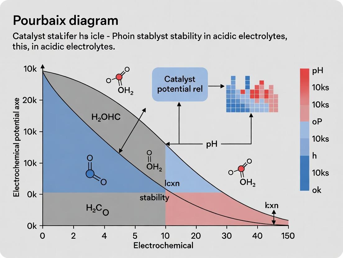
Decoding Catalyst Stability: A Practical Guide to Pourbaix Diagrams in Acidic Electrolytes
This comprehensive guide explores the critical role of Pourbaix diagrams in predicting and understanding electrocatalyst stability under harsh acidic conditions, crucial for applications like proton exchange membrane water electrolyzers (PEMWE)...
Decoding Catalyst Stability: A Practical Guide to Pourbaix Diagrams in Acidic Electrolytes
Abstract
This comprehensive guide explores the critical role of Pourbaix diagrams in predicting and understanding electrocatalyst stability under harsh acidic conditions, crucial for applications like proton exchange membrane water electrolyzers (PEMWE) and fuel cells. We begin with foundational electrochemical thermodynamics, explaining how to interpret potential-pH maps for metals, oxides, and novel catalyst materials. The article then details methodological approaches for constructing and applying these diagrams, including computational methods and in-situ validation techniques. We address common pitfalls in stability prediction and optimization strategies for real-world acidic environments. Finally, we compare computational predictions with experimental data, validating the diagram's power and limitations. Tailored for researchers and development professionals, this guide serves as an essential resource for designing durable catalysts for next-generation energy conversion and biomedical devices.
Pourbaix Diagrams Demystified: The Thermodynamic Blueprint for Acidic Catalyst Stability
Pourbaix diagrams, also known as potential-pH diagrams, are electrochemical phase maps that predict the thermodynamically stable phases of an element or compound as a function of electrode potential and solution pH. Within the context of broader research into catalyst stability in acidic electrolytes, these diagrams serve as an indispensable first-principles tool for predicting corrosion, passivation, and dissolution behavior. This whitepaper provides an in-depth technical guide to their construction, interpretation, and application in contemporary electrocatalysis research.
Fundamental Thermodynamic Basis
A Pourbaix diagram is constructed from the Nernst equation and the equilibrium constants for reactions involving the species of interest. The stability of a solid phase ( M ) in aqueous media is governed by three primary reaction types:
Redox Reactions (Potential-dependent): ( aA + mH^+ + ne^- \rightleftharpoons bB + cH_2O ) The Nernst equation applies: ( E = E^0 - \frac{0.0591}{n} \log Q ) at 298 K, where ( Q ) is the reaction quotient.
Acid-Base Reactions (pH-dependent): ( aA + mH^+ \rightleftharpoons bB ) The equilibrium is described by: ( \log K = \log([B]^b/[A]^a) - mpH ).
Solubility Reactions (Dependent on both): ( MmOn + 2nH^+ + 2ne^- \rightleftharpoons mM + nH_2O )
The lines on the diagram represent equilibria where the activities of the dissolved species are equal, typically set to a threshold like ( 10^{-6} ) M for practical "stability" against dissolution.
Table 1: Key Thermodynamic Parameters for Constructing a Pourbaix Diagram (Example: Platinum in Water)
| Reaction | ΔG° (kJ/mol) | E° vs. SHE (V) | Equilibrium Line Equation (E vs. pH) | Dominant Region |
|---|---|---|---|---|
| Pt²⁺ + 2e⁻ ⇌ Pt | 215.5 | ~1.18 | E = 1.18 + 0.0295 log[Pt²⁺] | Pt stable (low [Pt²⁺]) |
| PtO₂ + 4H⁺ + 4e⁻ ⇌ Pt + 2H₂O | -106.3 | 0.98 | E = 0.98 - 0.0591 pH | Pt stable (below line) |
| PtO₂ + 4H⁺ + 2e⁻ ⇌ Pt²⁺ + 2H₂O | -327.1 | 1.69 | E = 1.69 - 0.1182 pH + 0.0295 log[Pt²⁺] | PtO₂ / Pt²⁺ boundary |
| PtO₃²⁻ + 4H⁺ ⇌ PtO₂ + 2H₂O | - | - | log[PtO₃²⁻] = K - 4pH | PtO₂ / PtO₃²⁻ boundary |
Experimental Validation and Protocol for Catalyst Stability Mapping
Pourbaix diagrams predict thermodynamic stability, but kinetic factors dominate real catalyst performance. Experimental validation is critical.
Protocol: Inductively Coupled Plasma Mass Spectrometry (ICP-MS) for Dissolution Rate Measurement
Aim: Quantify the dissolution rate of a metallic catalyst (e.g., Pt, Ir) under potentiostatic control in acidic electrolyte (e.g., 0.1 M HClO₄).
Materials & Workflow:
- Electrochemical Cell: A 3-electrode cell with the catalyst-coated rotating disk electrode (RDE) as working electrode, reversible hydrogen electrode (RHE) as reference, and Pt mesh as counter.
- Electrolyte: High-purity 0.1 M HClO₄, deaerated with Argon for 30 min.
- Procedure: a. The electrolyte is held in a gas-tight cell with an outlet tube leading to the ICP-MS sample introduction system. b. Apply a constant potential (e.g., 1.0 V to 1.6 V vs. RHE) for a defined period (e.g., 2 hours). c. Use a peristaltic pump to continuously aspirate a small, constant stream (~0.5 mL/min) of the electrolyte from the cell directly into the ICP-MS nebulizer. d. The ICP-MS quantifies the concentration of dissolved metal ions (e.g., ( ^{195}\text{Pt}^+ )) in real-time with parts-per-trillion sensitivity. e. The dissolution rate (ng cm⁻² s⁻¹) is calculated from the steady-state concentration in the outlet, the flow rate, and the electrode geometric area.
- Data Correlation: Plot dissolution rate vs. applied potential. Compare "peaks" of dissolution to regions of predicted instability (e.g., Pt²⁺ stability field) on the Pourbaix diagram.
Protocol: In Situ X-ray Absorption Spectroscopy (XAS)
Aim: Determine the oxidation state and local coordination environment of catalyst atoms under operating conditions. Procedure:
- Prepare a catalyst thin film on a gas-diffusion layer or conductive polymer window.
- Mount in an in situ electrochemical XAS cell with X-ray transparent windows.
- Collect XANES (X-ray Absorption Near Edge Structure) spectra at specific potentials. The energy shift of the absorption edge indicates oxidation state (e.g., shift to higher energy for Pt(IV) vs. Pt(0)).
- Fit EXAFS (Extended X-ray Absorption Fine Structure) spectra to determine bond distances and coordination numbers, confirming the presence of oxide phases (Pt-O bonds) predicted by the Pourbaix diagram.
Diagram 1: Workflow for Validating Pourbaix Diagrams
Application to Catalyst Stability in Acidic Electrolytes
In proton exchange membrane water electrolyzers (PEMWE) and fuel cells (PEMFC), catalysts operate at low pH (≤1) and high anodic potentials (>1.5 V vs. RHE). The Pourbaix diagram for Ir, the state-of-the-art oxygen evolution reaction (OER) catalyst, reveals a critical insight: the stable phase is solid IrO₂, not metallic Ir. However, even IrO₂ can dissolve via formation of soluble Ir³⁺ or IrO₄²⁻ species at very high potentials or non-standard conditions.
Table 2: Stability Regions for Key Catalysts in Acidic Media (pH 0, 25°C)
| Catalyst | Stable Solid Phase (at OER potentials) | Soluble Species (Risk of Dissolution) | Key Stability Threshold (approx. vs. RHE) |
|---|---|---|---|
| Platinum (Pt) | Pt (metal) | Pt²⁺, PtO₃²⁻ (in very oxidizing, high pH) | Forms PtO₂ at >0.98 V; Pt dissolves as Pt²⁺ above ~1.1 V at high [H⁺]. |
| Iridium (Ir) | IrO₂ (oxide) | Ir³⁺, IrO₄²⁻ | Ir metal oxidizes to IrO₂ at ~0.92 V. IrO₂ may dissolve as Ir³⁺ at low potential or as IrO₄²⁻ at very high potential/pH. |
| Ruthenium (Ru) | RuO₂ (oxide) | Ru³⁺, RuO₄ | RuO₂ forms at ~0.79 V. High risk: RuO₂ oxidizes to volatile, soluble RuO₄ above ~1.4 V. |
| Gold (Au) | Au (metal) | Au⁺, Au³⁺ (complexed) | Stable metal phase up to ~1.5 V; dissolution requires complexing ions (e.g., Cl⁻). |
Advanced Considerations & Limitations
- Kinetics vs. Thermodynamics: Pourbaix diagrams are equilibrium maps. A predicted stable oxide (e.g., PtO₂) may form slowly, leaving the metal in a metastable state. Conversely, predicted dissolution may be negligibly slow.
- Complexing Agents & Anion Effects: Standard diagrams assume simple aqueous ions. Real electrolytes contain species (e.g., Cl⁻, SO₄²⁻) that complex metals, dramatically shifting stability fields. A separate diagram must be constructed for each defined electrolyte composition.
- Temperature & Crystallinity: Diagrams are typically for 25°C. High-temperature operation (e.g., 80°C in PEMFC) shifts equilibria. The crystalline phase of an oxide (e.g., anatase vs. rutile TiO₂) also has different stability.
Diagram 2: Factors Influencing Real Catalyst Stability
The Scientist's Toolkit: Key Research Reagent Solutions
Table 3: Essential Materials for Pourbaix & Catalyst Stability Studies
| Item | Function & Specification | Rationale |
|---|---|---|
| High-Purity Electrolyte | e.g., 0.1 M HClO₄ (TraceSELECT Ultra) | Minimizes impurity-induced dissolution or complexation. Perchlorate is weakly coordinating. |
| Reversible Hydrogen Electrode (RHE) | In-house or commercial, using same electrolyte. | Provides a potential reference tied to the solution's pH, essential for pH-potential diagrams. |
| Ultra-Pure Water | 18.2 MΩ·cm resistivity (from Milli-Q or similar). | Eliminates ionic contaminants that interfere with electrochemistry and ICP-MS analysis. |
| Single-Crystal Model Electrodes | e.g., Pt(111), Au(110) disks. | Provides a well-defined surface for fundamental studies linking structure to stability. |
| Nafion Binder Solution | 0.5% wt in low-alcohol solvent. | For preparing catalyst inks for thin-film working electrodes, ensuring proton conductivity. |
| ICP-MS Standard Solution | e.g., 1000 ppm Pt in 2% HNO₃. | For calibrating the ICP-MS to achieve quantitative, accurate dissolution measurements. |
| Calomel or Ag/AgCl Reference | Saturated KCl or 3 M NaCl filling solution. | Used when RHE is impractical; potential must be converted to RHE scale using pH. |
| Inert Gas Supply | Ultra-high purity Argon (≥99.999%). | For deaerating electrolytes to remove O₂, which interferes with redox measurements. |
This whitepaper provides a rigorous technical examination of the Nernst equation and Gibbs free energy, contextualized within research on catalyst stability using Pourbaix diagrams in acidic electrolytes. The principles discussed are foundational for interpreting electrochemical stability, dissolution potentials, and reaction spontaneity in proton-rich environments relevant to electrocatalysis and pharmaceutical development.
The stability and reactivity of catalytic materials in acidic media (e.g., PEM electrolyzers, biological compartments) are governed by electrochemical thermodynamics. The Gibbs free energy change (ΔG) of a reaction determines its spontaneity, while the Nernst equation quantitatively relates the reduction potential of an electrochemical half-cell to the standard electrode potential and the activities of the reacting species. In acidic electrolytes, the activity of H⁺ (pH) is a dominant variable.
The fundamental relationship is: ΔG = -nFE where n is the number of electrons transferred, F is Faraday's constant (96485 C/mol), and E is the cell potential. Under standard conditions (298.15 K, 1 bar, 1 M activity), this becomes ΔG° = -nFE°.
For a general reduction half-reaction: aOx + ne⁻ + cH⁺ ⇌ bRed + dH₂O The Nernst equation is expressed as:
[ E = E^{\circ} - \frac{RT}{nF} \ln \left( \frac{a{\text{Red}}^b \cdot a{\text{H}2\text{O}}^d}{a{\text{Ox}}^a \cdot a_{\text{H}^+}^c} \right) ]
At 298.15 K, using base-10 logs and assuming (a{\text{H}2\text{O}} \approx 1), this simplifies to:
[ E = E^{\circ} - \frac{0.0591}{n} \log \left( \frac{a{\text{Red}}^b}{a{\text{Ox}}^a} \right) - \frac{0.0591 \cdot c}{n} \text{pH} ]
The final term highlights the direct, linear dependence of potential on pH in acidic media, a cornerstone of Pourbaix diagram construction.
Quantitative Data: Key Thermodynamic Parameters
Table 1: Fundamental Constants and Conversion Factors
| Constant / Factor | Symbol | Value | Unit | Relevance |
|---|---|---|---|---|
| Faraday Constant | F | 96485.33212 | C mol⁻¹ | Converts moles e⁻ to charge |
| Gas Constant | R | 8.314462618 | J mol⁻¹ K⁻¹ | Relates energy, moles, & temp. |
| Standard Temp. | T | 298.15 | K | Reference temperature |
| Nernst Slope (298K) | (RT ln10)/F | 0.05916 | V | Prefactor in Nernst equation |
Table 2: Standard Reduction Potentials (E°) in Acidic Media (vs. SHE)
| Half-Reaction | E° (V) | Relevance to Catalyst Stability |
|---|---|---|
| 2H⁺ + 2e⁻ ⇌ H₂ | 0.000 (by definition) | Hydrogen evolution reaction (HER) reference |
| O₂ + 4H⁺ + 4e⁻ ⇌ 2H₂O | 1.229 | Oxygen reduction reaction (ORR) / water stability limit |
| Pt²⁺ + 2e⁻ ⇌ Pt(s) | ~1.18 | Platinum dissolution/redeposition |
| IrO₂(s) + 4H⁺ + 4e⁻ ⇌ Ir(s) + 2H₂O | ~0.98 | Iridium oxide stability for OER |
| Pd²⁺ + 2e⁻ ⇌ Pd(s) | 0.951 | Palladium dissolution potential |
Experimental Protocols for Key Measurements
Protocol: Determining the Reversible Potential via the Nernst Equation
Objective: To experimentally verify the Nernstian shift of a redox couple's potential with pH in acidic electrolyte. Materials: Electrochemical cell, working electrode (e.g., Pt disk), reference electrode (e.g., Ag/AgCl in 3M KCl), counter electrode (Pt mesh), potentiostat, buffer solutions (pH 0-6, 0.1 M ionic strength), analyte (e.g., 1 mM Quinone/Hydroquinone couple). Procedure:
- Prepare a series of acidic buffer solutions with precise pH values (e.g., 1.0, 2.0, 3.0, 4.0).
- Add an equal, low concentration (e.g., 1 mM) of both the oxidized and reduced forms of a reversible redox couple to each buffer.
- Assemble a three-electrode cell with the working electrode polished and cleaned.
- For each buffer, perform a low scan rate (e.g., 1 mV/s) cyclic voltammetry (CV) scan around the expected formal potential.
- Record the formal potential (E_f°) for each pH as the average of the anodic and cathodic peak potentials from the CV.
- Plot E_f° vs. pH. The slope should be -0.0591(c/n) V/pH, where *c is the number of H⁺ in the balanced half-reaction.
Protocol: Calculating ΔG for a Dissolution Reaction from Electrochemical Data
Objective: To calculate the Gibbs free energy change for a metal catalyst's dissolution (M → Mⁿ⁺ + ne⁻) in acidic media. Materials: Potentiostat, electrochemical cell, working electrode (catalyst of interest), relevant electrolyte, reference electrode. Procedure:
- Perform an anodic linear sweep voltammetry (LSV) scan (e.g., 0.5 mV/s) from the open circuit potential into the oxidative region.
- Identify the onset potential (E_onset) for a sustained anodic current, corresponding to M → Mⁿ⁺ + ne⁻.
- The reaction potential (Ereaction) under those specific conditions is approximated by Eonset.
- The ΔG for dissolution is calculated as: ΔG = nFE_reaction.
- To find the standard ΔG°, use the standard potential (E°_Mⁿ⁺/M) from literature: ΔG° = -nFE°.
- The activity of Mⁿ⁺ can then be related to the measured potential via the Nernst equation: Eonset ≈ E° + (RT/nF) ln(aMⁿ⁺).
Diagram: Relationship of Core Concepts in Acidic Stability
Diagram 1: Thermodynamic Control of Catalyst Stability in Acid
The Scientist's Toolkit: Key Research Reagent Solutions
Table 3: Essential Materials for Acidic Media Thermodynamics Research
| Reagent / Material | Function & Explanation |
|---|---|
| 0.1 M HClO₄ (Perchloric Acid) Electrolyte | Common acidic electrolyte for fundamental studies. Perchlorate anion has low specific adsorption, minimizing interference on electrode surfaces. |
| Saturated Calomel Electrode (SCE) or Ag/AgCl Reference | Stable reference electrode. Potential must be converted to the Standard Hydrogen Electrode (SHE) scale for thermodynamic analysis using a known offset (e.g., SCE = +0.241 V vs. SHE). |
| Nafion Membrane | Proton-exchange membrane used to separate electrode compartments while allowing H⁺ transport, mimicking PEM fuel cell/electrolyzer environments. |
| pH Buffers (e.g., Phosphate, Acetate, Sulfate) | Maintain constant proton activity (pH) during experiments, crucial for isolating pH effects as per the Nernst equation. |
| High-Purity Water (18.2 MΩ·cm) | Prevents contamination from ions that could alter electrochemical potentials or catalyze side reactions. |
| Quinhydrone (Quinone/Hydroquinone) | Reversible redox couple used as a internal potential standard to verify reference electrode potential or Nernstian behavior across pH. |
| Ultra-high Purity Inert Gas (Ar, N₂) | For deaerating electrolytes to remove dissolved O₂, which can interfere with measurements by introducing an additional redox couple (O₂/H₂O). |
The electrochemical stability of metal catalysts in acidic electrolytes is a cornerstone of modern electrochemical research, directly impacting fields from fuel cells to electrosynthesis. This guide contextualizes the key thermodynamic regions—immunity, corrosion, and passivation—within the framework of Pourbaix (E-pH) diagram analysis, a critical tool for predicting catalyst stability. Understanding these domains is essential for designing durable catalysts for proton-exchange membrane water electrolyzers (PEMWE) and acidic organic electrosynthesis, where harsh conditions prevail.
Thermodynamic Foundations: The Pourbaix Diagram
A Pourbaix diagram maps the thermodynamically stable phases of an element in an aqueous electrochemical system as a function of electrode potential (E) and pH. For metals in acidic electrolytes (typically pH < 7), three primary regions dictate stability.
Immunity: At sufficiently low potentials (highly reducing conditions), the metal remains in its metallic (M⁰) state, immune to oxidative dissolution. This is the ideal operational region for a stable catalyst. Corrosion: At higher potentials, the metal oxidizes to soluble ionic species (e.g., M²⁺(aq)), leading to catastrophic dissolution and catalyst degradation. Passivation: At even higher potentials, the metal may form an insoluble oxide or hydroxide layer (e.g., M₂O₃). This passive film can protect the bulk metal from further corrosion, but its stability (electronic conductivity, adherence) is critical for catalytic function.
Quantitative Stability Data for Key Catalytic Metals
The operational window for catalysts in acidic media (e.g., 0.1 M H₂SO₄, pH ~1) is defined by the hydrogen evolution reaction (HER, ~0 V vs. RHE) and oxygen evolution reaction (OER, ~1.23 V vs. RHE). Stability data for common metals are summarized below.
Table 1: Stability Regions of Select Metals in Acidic Electrolytes (vs. RHE, pH 0-1)
| Metal | Immunity Region (V vs. RHE) | Primary Corrosion Product | Passivation Region (V vs. RHE) | Passivation Layer | Key Catalyst Use |
|---|---|---|---|---|---|
| Platinum (Pt) | < ~0.8 - 1.1 | Pt²⁺ (minimal) | > ~1.1 | PtO₂ (thin, reversible) | HER, ORR, anode catalyst support. |
| Iridium (Ir) | < ~0.9 - 1.3 | IrO₂²⁺ (slow) | > ~1.3 | IrO₂ (conductive, stable) | OER catalyst. |
| Gold (Au) | < ~1.4 | Au⁺ (complexed) | > ~1.4 | Au₂O₃ (unstable) | ORR, inert substrate. |
| Copper (Cu) | < ~0.1 | Cu²⁺ | ~0.1 to ~0.6 | Cu₂O / CuO | CO₂ reduction (requires protection). |
| Nickel (Ni) | < ~0.1 | Ni²⁺ | > ~0.4 (pH-dependent) | NiO / Ni(OH)₂ | Not stable in strong acid. |
Table 2: Experimental Corrosion Rates in 0.5 M H₂SO₄ at 25°C
| Metal | Applied Potential (V vs. RHE) | Region | Measured Corrosion Rate (µA/cm²) | Equivalent Dissolution (ng/cm²·s) | Method |
|---|---|---|---|---|---|
| Polycrystalline Pt | 1.0 | Immunity/Onset Passivation | 0.01 - 0.05 | ~0.5 - 2.5 | ICP-MS |
| Polycrystalline Ir | 1.5 | Passivation | 0.1 - 0.3 | ~9.6 | ICP-MS |
| Polycrystalline Cu | 0.3 | Corrosion | > 100 | > 3300 | RDE Mass Loss |
Key Experimental Protocols for Stability Assessment
Protocol 1: Inductively Coupled Plasma Mass Spectrometry (ICP-MS) for Dissolution Measurement
- Objective: Quantify trace metal ion dissolution from an electrode during electrochemical cycling.
- Materials: Working electrode (catalyst on substrate), acidic electrolyte (e.g., 0.1 M HClO₄), electrochemical cell, ICP-MS.
- Procedure:
- Clean all cell components with aqua regia and ultrapure water (18.2 MΩ·cm).
- Fill cell with a known volume (e.g., 10 mL) of purified electrolyte.
- Perform electrochemical protocol (e.g., chronoamperometry, cyclic voltammetry).
- Post-experiment, collect the entire electrolyte volume.
- Acidify the sample with ultrapure HNO₃ to 2% v/v.
- Analyze using ICP-MS with external calibration standards.
- Calculate dissolution rate:
Rate (mol/s) = (Concentration (mol/L) * Volume (L)) / Time (s).
Protocol 2: In-situ Electrochemical Quartz Crystal Microbalance (EQCM)
- Objective: Monitor mass changes on an electrode in real-time with nanogram sensitivity.
- Materials: EQCM with Au-coated quartz crystal, catalyst coating station, potentiostat compatible with EQCM.
- Procedure:
- Coat the EQCM crystal with a thin, adherent layer of the catalyst material.
- Calibrate the frequency shift (Δf) to mass change (Δm) using Sauerbrey equation:
Δm = -C * Δf, where C is the sensitivity constant. - Immerse the crystal in the acidic electrolyte under potential control.
- Apply potential steps or sweeps while simultaneously recording current and frequency.
- A frequency increase indicates mass loss (dissolution); a decrease indicates mass gain (oxide formation or deposition).
The Scientist's Toolkit: Key Research Reagent Solutions
Table 3: Essential Materials and Reagents for Acidic Stability Studies
| Item | Function / Rationale | Key Consideration for Stability Studies |
|---|---|---|
| Perchloric Acid (HClO₄), Ultra Pure | Common electrolyte (0.1 M). Low specific adsorption minimizes anion interference. | Highly oxidative when hot/concentrated. Must be used with extreme caution and proper training. |
| Sulfuric Acid (H₂SO₄), Ultra Pure | Common electrolyte (0.5 M). Relevant to PEMWE conditions. | Sulfate anions can adsorb on some metals, influencing reactivity and oxide formation. |
| Hydrochloric Acid (HCl), TraceMetal Grade | Electrolyte for specific studies; used for cleaning. | Chloride anions aggressively promote corrosion and complex metal ions, altering stability regions. |
| Aqua Regia (3:1 HCl:HNO₃) | Powerful oxidizing mixture for cleaning glassware and etching electrodes. | Extremely hazardous. Must be prepared fresh in a fume hood; never store. |
| High-Purity Water (18.2 MΩ·cm) | Solvent for all electrolytes. Reduces impurity-driven side reactions. | Use from a certified ultrapure system; resistivity is a key quality indicator. |
| Nafion Perfluorinated Resin | Binder for catalyst inks on rotating disk electrodes (RDEs). | Can introduce sulfonic acid groups/local acidity; use consistent, minimal amounts (e.g., 0.02-0.1% wt). |
| Single-Crystal Metal Electrodes (Pt, Au, etc.) | Model systems with well-defined surfaces. | Enable fundamental studies linking stability to specific crystallographic facets. |
| Indium Tin Oxide (ITO) or Fluorinated Tin Oxide (FTO) Glass | Transparent conducting substrate for spectroelectrochemistry. | Allows in-situ optical monitoring of corrosion/passivation (e.g., UV-Vis). |
Within the context of Pourbaix diagram catalyst stability research for acidic electrolytes (e.g., PEM electrolyzers, acidic CO₂ reduction), understanding the non-equilibrium solubility of metal ions and solid phases under high proton activity is paramount. Standard solubility product constants (K_sp) fail under highly acidic, non-equilibrium conditions where proton-coupled dissolution kinetics and the formation of soluble aquo- and chloro-complexes dominate. This guide details the mechanisms, experimental protocols, and material considerations essential for researchers investigating catalyst durability and metal ion contamination in acidic media.
Mechanisms of Proton-Coupled Dissolution
Under high [H⁺], two primary pathways enhance the solubility of metal oxides, hydroxides, and even some sparingly soluble salts:
2.1. Direct Proton Attack: M–O–M + H⁺ → M–OH–M⁺ (surface protonation) M–OH–M⁺ + H⁺ → 2M⁺ + H₂O (lattice cleavage) This pathway is critical for oxide catalysts (e.g., IrO₂, RuO₂) in oxygen evolution reaction (OER).
2.2. Ligand-Assisted Dissolution: In chloride-containing acidic electrolytes (common in many industrial processes), dissolution is accelerated: MxOy + yH⁺ + zCl⁻ → MCl_z^(y-2z) + (y/2)H₂O This leads to stable complexes like [PtCl₆]²⁻ or [PdCl₄]²⁻, drastically increasing effective solubility.
Key Experimental Protocols
3.1. Inductively Coupled Plasma Mass Spectrometry (ICP-MS) for Solubility Quantification Protocol:
- Electrolyte Preparation: Prepare 0.1 M H₂SO₄ (or other relevant acid) with/without 0.1 M NaCl. Purge with Ar to remove dissolved CO₂.
- Material Exposure: Add 100 mg of catalyst powder (e.g., 20 wt% Pt/C, IrO₂ nanopowder) to 50 mL of electrolyte in a PTFE vial.
- Conditioning: Place in a temperature-controlled shaker at 80°C (simulating accelerated conditions) for 24-168 hours.
- Separation: After exposure, filter the suspension through a 20 nm alumina membrane syringe filter.
- Acidification: Acidify the filtrate with 2% ultrapure HNO₃.
- Analysis: Analyze via ICP-MS against a calibration curve. Use internal standards (e.g., ¹¹⁵In, ¹⁸⁷Re) for signal drift correction. Data Output: Total dissolved metal concentration (ppb or µg/L).
3.2. Electrochemical Flow Cell Coupled to ICP-MS (EC-ICP-MS) Protocol:
- Cell Setup: Integrate a flow-through electrochemical cell (with a known catalyst-coated working electrode) directly upstream of the ICP-MS nebulizer.
- Electrolyte Flow: Use a peristaltic pump to circulate acidic electrolyte (e.g., 0.05 M H₂SO₄) at 0.5 mL/min.
- Potential Control: Hold the working electrode at a fixed potential relevant to operation (e.g., 1.8 V vs. RHE for OER).
- Time-Resolved Monitoring: The ICP-MS records real-time dissolution signals (e.g., ¹⁹⁵Pt, ¹⁹³Ir) synchronized with electrochemical data. Data Output: Dissolution rate (ng cm⁻² s⁻¹) as a function of applied potential.
Table 1: Solubility of Selected Catalyst Materials in Acidic Electrolyte (0.1 M H₂SO₄, 80°C, 24h)
| Material | Phase | Measured Total Dissolved Metal (µg/L) | Log(K_sp) of Corresponding Hydroxide |
|---|---|---|---|
| Platinum | Pt(0) / PtO₂ | 15.2 (Pt) | ~ -38 (Pt(OH)₂) |
| Iridium Dioxide | IrO₂ | 842.7 (Ir) | ~ -12 (Ir(OH)₄) |
| Ruthenium Dioxide | RuO₂ | 12,450 (Ru) | ~ -6 (Ru(OH)₄) |
| Gold | Au(0) | < 0.1 (Au) | - |
| Titanium (substrate) | TiO₂ (anatase) | 8.5 (Ti) | ~ -29 (Ti(OH)₄) |
Table 2: Effect of Chloride on Dissolution Rate (EC-ICP-MS at 1.4 V vs. RHE)
| Catalyst | Electrolyte | Dissolution Rate (ng cm⁻² s⁻¹) |
|---|---|---|
| Pt Nanoparticles | 0.1 M HClO₄ | 0.001 |
| Pt Nanoparticles | 0.1 M HClO₄ + 10 mM NaCl | 0.157 |
| IrO₂ thin film | 0.05 M H₂SO₄ | 0.012 |
| IrO₂ thin film | 0.05 M H₂SO₄ + 10 mM NaCl | 0.089 |
Visualization of Pathways and Workflows
The Scientist's Toolkit: Research Reagent Solutions
Table 3: Essential Materials for Acidic Solubility Studies
| Item | Function & Specification | Critical Note |
|---|---|---|
| Ultrapure Acids | For electrolyte prep and sample acidification. Trace metal grade HNO₃, H₂SO₄, HClO₄. | Baseline metal contamination must be < 1 ppt for target analytes. |
| High-Purity Salts | For supporting electrolyte and complexation studies (e.g., NaCl, Na₂SO₄). 99.999% purity. | Minimizes introduction of competing cationic impurities. |
| PTFE Vials & Filters | All sample digestion, storage, and filtration must use PTFE or PFA materials. | Precludes leaching of silicate from glass and adsorption onto glass walls. |
| ICP-MS Calibration Standards | Multi-element standard solutions, customized for catalyst metals (Pt, Pd, Ir, Ru, Au, Ti, etc.). | Must be matrix-matched to the acidic electrolyte. |
| Certified Reference Material (CRM) | e.g., NIST 1643f (Trace Elements in Water). | Used for validating ICP-MS method accuracy and recovery. |
| Membrane Filters | Anodized alumina or polyethersulfone (PES) syringe filters, 20 nm pore size. | For complete separation of nanoparticulate catalyst from dissolved species. |
| Potentiostat & Electrochemical Cell | For controlled potential experiments. Cell must be all-PTFA or PEEK with minimal metal parts. | Avoids corrosion of cell components contributing to background signal. |
This whitepaper addresses a central pillar of a broader thesis on Pourbaix Diagram Catalyst Stability in Acidic Electrolytes Research. The design of durable, active catalysts for applications in proton-exchange membrane electrolyzers, fuel cells, and electrosynthesis necessitates a rigorous understanding of material stability under operating conditions. A critical challenge is identifying the stable chemical phases of catalytic active sites under low pH (high proton activity) and applied potential. This guide details the theoretical framework, experimental protocols, and analytical tools required to pinpoint these critical points of stability, where the catalytically active phase persists without dissolution or passivation.
Theoretical Framework: Pourbaix Diagrams at Low pH
The Pourbaix diagram (potential-pH diagram) is an electrochemical phase map that plots the thermodynamically stable phases of an element or compound as a function of electrode potential (E) and pH. At low pH (< 4), the high concentration of H⁺ ions shifts equilibria, making dissolution to aqueous cations (e.g., Mⁿ⁺) a dominant deactivation pathway for many metals.
Key Regions at Low pH:
- Immunity: The metallic (M⁰) phase is stable. The catalyst remains in its reduced, metallic form.
- Corrosion/Dissolution: The aqueous ion (Mⁿ⁺) is the stable species. The active site leaches into the electrolyte, leading to irreversible catalyst loss.
- Passivation: A solid oxide, hydroxide, or hydrous oxide (MₓOᵧ, M(OH)₂) is stable. This can form a protective layer or a catalytically inactive barrier.
The "critical point" for a catalytic active site is often the boundary between the Immunity and Passivation regions, where the surface may be optimally active and stable. The boundary between Immunity and Corrosion is a critical failure point.
Key Quantitative Data & Stability Thresholds
Recent computational and experimental studies provide critical data for common catalytic elements in acidic media (pH 0-3, 25°C). The following tables summarize stability thresholds.
Table 1: Thermodynamic Stability of Selected Catalytic Elements at pH = 0
| Element | Stable Metallic Phase (Immunity) Potential Range (vs. SHE) | Primary Dissolution Product (Corrosion) | Passivating Oxide Phase |
|---|---|---|---|
| Platinum (Pt) | E > ~0.98 V | Pt²⁺, PtO₂²⁻ (at high E) | PtO₂ (above ~0.98 V) |
| Iridium (Ir) | E > ~0.926 V | Ir³⁺, IrO₃²⁻ (at high E) | IrO₂ (above ~0.926 V) |
| Ruthenium (Ru) | E > ~0.68 V | Ru³⁺, RuO₄²⁻ | RuO₂ (above ~0.68 V, unstable to OER) |
| Palladium (Pd) | E > ~0.92 V | Pd²⁺ | PdO (above ~0.92 V) |
| Gold (Au) | E > ~1.50 V | Au⁺, Au³⁺ | Au₂O₃ (above ~1.50 V) |
Table 2: Experimentally Observed Dissolution Rates in 0.1 M HClO₄ at 1.2 V vs. RHE
| Catalyst Material | Dissolution Rate (ng cm⁻² h⁻¹) | Dominant Mechanism | Reference (Year) |
|---|---|---|---|
| Pt nanoparticles (5 nm) | 15 - 25 | Transient during oxide formation/reduction | Cherevko et al. (2014) |
| IrO₂ (film) | < 1 | Steady-state, potential-dependent | Geiger et al. (2018) |
| RuO₂ (film) | 250 - 500 | Severe during OER, forms volatile RuO₄ | Geiger et al. (2018) |
| Pd nanoparticles | 80 - 120 | Continuous, especially during oxide formation | Povia et al. (2021) |
Experimental Protocols for Identification
In Situ/Operando X-ray Absorption Spectroscopy (XAS)
Objective: Determine the oxidation state and local coordination geometry of the active site under working conditions.
Detailed Protocol:
- Cell Preparation: Use a custom-designed electrochemical flow cell with X-ray transparent windows (e.g., Kapton, carbon).
- Electrode Fabrication: Deposit catalyst ink (catalyst powder, Nafion ionomer, isopropanol) onto a porous carbon paper or a glassy carbon disc. Loadings typically 0.1-1.0 mg catalyst cm⁻².
- Electrolyte & Setup: Use 0.1 M HClO₄ (high purity) as the acidic electrolyte. A standard three-electrode setup is used: catalyst as working electrode, reversible hydrogen electrode (RHE) as reference, and Pt mesh as counter electrode.
- Data Acquisition:
- Secure the cell in the XAS beamline.
- Apply a series of constant potentials (e.g., 0.4 V to 1.6 V vs. RHE) representing the operational window.
- At each potential hold, acquire both X-ray Absorption Near Edge Structure (XANES) and Extended X-ray Absorption Fine Structure (EXAFS) spectra.
- Simultaneously record electrochemical current.
- Data Analysis: Fit XANES spectra to linear combinations of reference spectra (e.g., metal foil, metal oxide) to quantify phase composition. Fit EXAFS spectra to obtain bond distances and coordination numbers.
Online Inductively Coupled Plasma Mass Spectrometry (ICP-MS)
Objective: Quantify dissolution of catalyst material in real-time with ultra-high sensitivity.
Detailed Protocol:
- System Configuration: Integrate the electrochemical cell outlet directly into the nebulizer of the ICP-MS via PTFE tubing. A peristaltic pump maintains a constant electrolyte flow (e.g., 0.2 mL min⁻¹).
- Electrode & Cell: Use a rotating disc electrode (RDE) configuration to ensure homogeneous mass transport. The cell must be gas-tight and purged with inert gas (Ar).
- Experimental Sequence:
- Begin with electrolyte flow and ICP-MS stabilization while holding potential at open circuit voltage (OCV).
- Initiate a potential program (e.g., cyclic voltammetry, chronoamperometry at fixed potentials).
- The ICP-MS continuously monitors selected isotope signals (e.g., ¹⁹⁵Pt, ¹⁹³Ir, ¹⁰¹Ru) with a time resolution of ~1-10 seconds.
- Calibration: Perform post-experiment calibration by injecting standard solutions of known concentration into the electrolyte stream.
Electrochemical Stability Assessment via Cyclic Voltammetry
Objective: Rapidly screen for electrochemical signatures of dissolution, oxide formation/reduction, and phase transitions.
Detailed Protocol:
- Electrode Preparation: Use a thin-film rotating ring-disc electrode (RRDE). The catalyst is coated on the glassy carbon disc. The Pt ring is used to detect dissolved species (collection experiments).
- Stability Protocol:
- Record initial stable cyclic voltammogram (CV) in a non-activating window (e.g., 0.05 - 0.4 V vs. RHE) to establish baseline.
- Perform accelerated stress tests (AST) by scanning repeatedly over a wide potential range (e.g., 0.05 - 1.6 V vs. RHE at 500 mV s⁻¹ for 1000 cycles).
- Periodically return to the initial non-activating window to record CVs and monitor changes in electrochemically active surface area (ECSA) via hydrogen underpotential deposition (Hupd) or oxide stripping charge.
- Analysis: The loss of ECSA and changes in oxide formation/reduction peaks indicate corrosion or phase transformation.
Visualization of Methodologies
Diagram 1: Experimental Workflow for Identifying Critical Points
Diagram 2: Low pH Stability Decision Pathway
The Scientist's Toolkit: Essential Research Reagents & Materials
| Item | Function/Description | Critical Specification |
|---|---|---|
| High-Purity HClO₄ (e.g., 70%, TraceSELECT) | Standard acidic electrolyte. Low chloride and metal impurities prevent misleading corrosion data. | < 1 ppb total metallic impurities. |
| Reversible Hydrogen Electrode (RHE) | The reference electrode for all potential measurements in acidic media. Provides a pH-independent reference scale. | Must be calibrated frequently in clean electrolyte. |
| Nafion Ionomer Solution (5% wt) | Binds catalyst particles to the electrode substrate and provides proton conductivity. | Dilute to 0.05-0.5% wt in alcohol for ink preparation. |
| X-ray Transparent Window Film (e.g., Kapton) | Forms the window of operando electrochemical cells for XAS and XRD, minimizing X-ray absorption. | High chemical resistance, specific thickness (e.g., 25 µm). |
| ICP-MS Tuning Solution (e.g., 1 ppb Ce, Co, Li, Tl, Y) | Optimizes ICP-MS instrument sensitivity and mass calibration before dissolution experiments. | Must contain elements covering low, mid, and high mass ranges. |
| Isotopically Enriched Catalyst Tracers | Used in model studies to differentiate between dissolution from different catalyst components or layers via ICP-MS. | e.g., ¹⁹⁴Pt, ¹⁰⁵Pd. |
| Single-Crystal Metal Electrodes (Pt(hkl), Au(hkl), etc.) | Provide atomically defined surfaces as model systems to understand fundamental phase stability without nanoparticle complexity. | Orientation accuracy within 0.5°. |
From Theory to Bench: Building and Applying Pourbaix Diagrams for Acid-Stable Catalyst Design
Within the context of research on catalyst stability in acidic electrolytes, Pourbaix diagrams are indispensable predictive tools. These potential-pH maps define the domains of thermodynamic stability for metals, their oxides, hydroxides, and dissolved ions. For electrocatalyst design—particularly for reactions like the oxygen evolution reaction (OER) in proton exchange membrane electrolyzers—the diagram identifies potential-pH conditions where the catalyst remains stable or may corrode, guiding material selection and operational parameter optimization.
Theoretical Foundation
The Pourbaix diagram is constructed from the Nernst equation and mass-balance constraints. The key governing equations are:
For redox reactions not involving H⁺ or OH⁻:
E = E⁰ - (0.05916/n) * log(Q)at 298.15 K.For reactions involving H⁺:
E = E⁰ - (0.05916*m/n)*pH - (0.05916/n) * log(Q), where m is the number of H⁺ ions.For pH-dependent hydrolysis/precipitation: A horizontal, vertical, or sloped line represents the equilibrium boundary.
The overall stability field is determined by comparing the Gibbs free energy of formation (ΔGf⁰) for all possible species.
Step-by-Step Construction Methodology
Step 1: Define the System and Gather Data
Select the element (e.g., Pt, Ir, Ni) and all plausible species in aqueous systems (e.g., M, M₂O₃, M⁺, MO₄²⁻). Gather standard Gibbs free energy of formation (ΔGf⁰) data for each species from reliable thermodynamic databases like the NIST JANAF tables or CRC Handbook. Recent computational databases (e.g., Materials Project) can supplement experimental data.
Table 1: Exemplary Thermodynamic Data for Iridium at 298.15 K
| Species | State | ΔGf⁰ (kJ/mol) | Reference / Notes |
|---|---|---|---|
| Ir | s | 0.0 | Defined reference |
| IrO₂ | s | -188.5 | Key oxide for OER catalysts |
| Ir³⁺ | aq | +130.5 | Assumed value for demonstration |
| IrO₄²⁻ | aq | +150.2 | Assumed value for demonstration |
| H₂O | l | -237.18 | Required for all aqueous equilibria |
Step 2: Enumerate All Relevant Reactions
Formulate balanced electrochemical and chemical reactions for each phase boundary. For Ir in water, critical reactions include:
- IrO₂ + 4H⁺ + 4e⁻ ⇌ Ir + 2H₂O (Reduction of oxide)
- Ir³⁺ + 3e⁻ ⇌ Ir (Metal ion reduction)
- IrO₂ + 4H⁺ + 2e⁻ ⇌ Ir³⁺ + 2H₂O (Oxide dissolution)
- IrO₄²⁻ + 8H⁺ + 6e⁻ ⇌ Ir + 4H₂O (Oxoanion reduction)
- 2IrO₂ + 2H₂O ⇌ 2IrO₄²⁻ + 4H⁺ + 4e⁻ (Oxide to oxoanion)
Step 3: Calculate Equilibrium Equations
Calculate the standard potential (E⁰) for each electrochemical reaction using ΔG⁰rxn = -nFE⁰. Express the equilibrium condition as E = f(pH, log[activity]).
Table 2: Derived Equilibrium Equations for the Ir-H₂O System
| Reaction No. | Equilibrium Equation (E vs. SHE) | Boundary Type |
|---|---|---|
| 1 | E = 1.02 - 0.0591*pH | Sloped (Ir/IrO₂) |
| 2 | E = 0.45 - 0.0591*log[Ir³⁺] | Horizontal (Ir³⁺/Ir) |
| 3 | E = 1.08 - 0.1182pH + 0.0197log[Ir³⁺] | Sloped (IrO₂/Ir³⁺) |
| 4 | E = 0.97 - 0.0788pH + 0.00985log[IrO₄²⁻] | Sloped (Ir/IrO₄²⁻) |
| 5 | E = 1.04 - 0.0788pH - 0.0197log[IrO₄²⁻] | Sloped (IrO₂/IrO₄²⁻) |
Note: Calculations assume a dissolved species activity of 10⁻⁶ M, a typical threshold for corrosion.
Step 4: Plot Boundaries and Define Stability Regions
Using the equations from Table 2, plot lines on an E (y-axis, V vs. SHE) vs. pH (x-axis, 0-14) grid. The intersection of lines defines triple points. The region with the lowest Gibbs free energy for a given (E, pH) coordinate is the dominant species.
Step 5: Incorporate the Stability Domain of Water
Superimpose the water stability lines:
- Upper limit (O₂ evolution): E = 1.23 - 0.0591*pH
- Lower limit (H₂ evolution): E = 0.00 - 0.0591*pH Catalyst operation must consider overpotentials beyond these lines.
Experimental Protocol: Validating Diagram Predictions
To verify the predicted corrosion boundaries for a catalyst (e.g., IrO₂ film on a Ti substrate) in acidic electrolyte (0.5 M H₂SO₄, pH ~0.3).
Materials:
- Working Electrode: Sputtered IrO₂ on Ti disk (0.196 cm²).
- Counter Electrode: Pt mesh.
- Reference Electrode: Reversible Hydrogen Electrode (RHE) in the same electrolyte.
- Electrolyte: 0.5 M H₂SO₄, purged with N₂.
- Instrumentation: Potentiostat, ICP-MS.
Procedure:
- Electrochemical Setup: Assemble a 3-electrode cell. Record open circuit potential (OCP) for 30 min.
- Potentiodynamic Scan: Perform a slow anodic scan (0.1 mV/s) from OCP to 1.8 V vs. RHE. Monitor current for oxidation/dissolution.
- Potentiostatic Hold: Hold the electrode at a series of fixed potentials (e.g., 1.4 V, 1.6 V, 1.8 V vs. RHE) for 2 hours each. Continuously monitor current.
- Solution Analysis: After each hold, collect a 5 mL aliquot of electrolyte. Analyze via ICP-MS to quantify dissolved Ir concentration.
- Data Correlation: Plot measured Ir dissolution rate (from ICP-MS) vs. applied potential. Compare the onset potential for significant dissolution to the predicted boundary between IrO₂ and IrO₄²⁻ or Ir³⁺ on the constructed Pourbaix diagram.
Visualizing the Construction Workflow
Title: Pourbaix Diagram Construction and Validation Workflow
The Scientist's Toolkit: Key Research Reagents & Materials
Table 3: Essential Materials for Pourbaix Analysis & Validation
| Item | Function/Brief Explanation |
|---|---|
| High-Purity Deionized Water (18.2 MΩ·cm) | Prevents contamination in electrolyte preparation for accurate potential measurement. |
| Ultrapure Acids/Bases (e.g., H₂SO₄, HClO₄, KOH) | For precise pH control and electrolyte formulation. |
| Reversible Hydrogen Electrode (RHE) | The essential reference electrode in aqueous electrochemistry; its potential scales with pH. |
| Inert Gas Supply (Argon, Nitrogen) | For deaerating electrolytes to remove interfering O₂. |
| Inductively Coupled Plasma Mass Spectrometry (ICP-MS) Standards | Calibration standards for quantitative analysis of dissolved metal ions from corrosion. |
| Standard Thermodynamic Database (e.g., NIST JANAF, HSC Chemistry) | Source of reliable ΔGf⁰, S⁰, and Cp data for calculations. |
| Electrochemical Cell (3-electrode) | With separated compartments to prevent contamination of reference electrode. |
Within the broader thesis investigating catalyst stability in acidic electrolytes for applications such as proton exchange membrane electrolyzers and fuel cells, Pourbaix diagrams serve as indispensable thermodynamic maps. These diagrams plot the stable phases of an element or material as a function of applied potential and pH. Traditional experimental construction is laborious and often impractical for novel, multi-element materials. Density Functional Theory (DFT) provides a powerful computational framework to predict these diagrams ab initio, accelerating the discovery and screening of corrosion-resistant, electrochemically stable catalysts for harsh acidic environments.
Theoretical Foundation: From DFT to Pourbaix Diagram
The Pourbaix diagram is constructed from the minimization of Gibbs free energy. For an electrochemical system, the relevant thermodynamic potential is the grand canonical potential. DFT calculates the electronic energy of solid and gaseous species, which is then corrected to Gibbs free energy using vibrational, rotational, and translational contributions (for molecules) and the computational hydrogen electrode (CHE) model for proton/electron transfers.
Key Equation (CHE Model): The free energy of a proton-electron pair (H⁺ + e⁻) is referenced to half that of H₂ gas at standard conditions: G(H⁺ + e⁻) = 1/2 G(H₂). The effect of potential (U) and pH is incorporated via: ΔG = ΔG⁰ - neU + _kBT * ln(10) * pH where _ne is the number of electrons transferred.
Diagram Construction Protocol:
- DFT Calculations: Perform geometry optimization and energy calculations for all considered solid phases (pure elements, oxides, hydroxides, etc.), aqueous ions, and water/gas molecules (H₂, O₂).
- Free Energy Corrections: Apply zero-point energy, thermal, and entropic corrections to DFT total energies to obtain G(298 K, 1 bar).
- Aqueous Ion Reference: The free energy of aqueous ions is typically anchored to experimental solvation energies or calculated using implicit solvation models (e.g., VASPsol).
- Phase Stability Determination: For each (U, pH) coordinate, calculate the formation free energy for all possible phases and select the most stable one.
- Boundary Calculation: Solve for the (U, pH) lines where the stability of two phases is equal.
Table 1: Key DFT Parameters for Pourbaix Diagram Construction
| Parameter | Typical Setting/Value | Purpose/Justification |
|---|---|---|
| Exchange-Correlation Functional | PBE, RPBE, SCAN, HSE06 | Determines electron-electron interaction accuracy. PBE is common for solids. |
| Plane-Wave Cutoff Energy | 400-600 eV | Basis set size; ensures convergence of total energy. |
| k-point Mesh Density | Γ-centered, ~30 Å⁻¹ resolution | Samples Brillouin zone for bulk solids. |
| Pseudopotential | Projector Augmented-Wave (PAW) | Represents core electrons efficiently. |
| Energy Convergence Criterion | ≤ 1×10⁻⁵ eV/atom | Ensures electronic step precision. |
| Force Convergence Criterion | ≤ 0.01 eV/Å | Ensures ionic relaxation accuracy. |
| Solvation Model | VASPsol, implicit solvent | Estimates aqueous ion and surface hydration energies. |
| Reference for H⁺/e⁻ | Computational Hydrogen Electrode (CHE) | Links electron/proton chemical potential to H₂. |
Computational Workflow for DFT-Pourbaix Generation
The following diagram outlines the standard computational pipeline.
Diagram 1: DFT Pourbaix Calculation Workflow
Experimental Validation Protocol for Computational Diagrams
DFT-calculated diagrams require experimental validation, particularly for novel materials.
Protocol: In-situ Electrochemical Stability Mapping
- Electrode Preparation: Synthesize the novel material (e.g., via hydrothermal, sol-gel, or sputtering). Deposit as a thin film or prepare an ink for coating onto an inert rotating disk electrode (e.g., glassy carbon).
- Electrochemical Cell Setup: Use a standard three-electrode cell with the material as working electrode, a reversible hydrogen electrode (RHE) as reference (critical for pH correction), and a Pt mesh counter electrode. Use a N₂ or Ar-purged acidic electrolyte (e.g., 0.5 M H₂SO₄, pH ~0.3).
- Potentiostatic Hold Experiment:
- Set the cell potential to a value within a predicted stable region (e.g., 0.8 V vs. RHE). Hold for 1-2 hours while monitoring current.
- Use Inductively Coupled Plasma Mass Spectrometry (ICP-MS) to analyze electrolyte for dissolved metal ions.
- Ex-situ characterize the electrode surface post-hold via X-ray Photoelectron Spectroscopy (XPS) and Scanning Electron Microscopy (SEM).
- Cyclic Voltammetry (CV) Stability Screening: Cycle the potential across a range spanning predicted phase boundaries (e.g., 0.05 to 1.5 V vs. RHE, 50 mV/s). Observe changes in CV shape over 100-1000 cycles, indicating corrosion or phase transformation.
- Correlate Data: Compare dissolution rates (from ICP-MS) and surface composition changes (from XPS) with the predicted stable/ unstable regions from the DFT-Pourbaix diagram.
Table 2: Quantitative Experimental Validation Data for Hypothetical Novel Anode Catalyst (M₁M₂Oₓ) in 0.5 M H₂SO₄
| Applied Potential (V vs. RHE) | DFT-Predicted Stable Phase | ICP-MS Dissolution Rate (ng cm⁻² h⁻¹) M₁ / M₂ | Post-Hold XPS Surface Phase | Experimental Stability Verdict |
|---|---|---|---|---|
| 0.4 | M₁O₂ + M₂ | 0.8 / 12.5 | M₁O₂, M₂ metallic | Partially Stable (M₂ leaches) |
| 0.9 | M₁M₂O₄ (spinel) | 1.2 / 1.5 | M₁M₂O₄ dominant | Stable |
| 1.4 | M₁O₃ + M₂O₃ | 45.0 / 8.7 | M₁O₃, amorphous M₂-oxyhydroxide | Unstable (High dissolution) |
The Scientist's Toolkit: Essential Research Reagents & Materials
Table 3: Key Research Reagent Solutions for Experimental Pourbaix Validation
| Item | Function/Brief Explanation |
|---|---|
| High-Purity Acid Electrolytes (e.g., H₂SO₄, HClO₄) | Provide the acidic medium (pH 0-3). High purity minimizes contaminant interference. |
| Reversible Hydrogen Electrode (RHE) | The essential reference electrode for acidic work, as its potential scales with pH. |
| Rotating Disk Electrode (RDE) Setup | Enables controlled mass transport, isolating intrinsic material stability from diffusion limits. |
| Inductively Coupled Plasma Mass Spectrometry (ICP-MS) | Detects trace-level dissolution of catalyst components into the electrolyte (ppt-ppb sensitivity). |
| In-situ/Operando Raman or FTIR Spectroelectrochemistry Cell | Probes molecular structure and adsorbates on the catalyst surface during potential hold. |
| Projector Augmented-Wave (PAW) Pseudopotential Library | The foundational set of atomic potentials for accurate DFT calculations in VASP, ABINIT, etc. |
| Materials Project/ OQMD Database API | Allows retrieval of computed DFT energies for known phases, serving as benchmarks or inputs. |
| Implicit Solvation Software (VASPsol, SIESTA sol) | Computes solvation free energies for aqueous ions, critical for accurate Pourbaix boundaries. |
Advanced Application: Multi-Element Systems and Kinetic Extensions
For complex catalysts (e.g., high-entropy alloys, doped perovskites), the diagram becomes multi-dimensional. The stable phase is determined by minimizing the total free energy subject to element conservation.
Diagram for Multi-Element Stability Analysis:
Diagram 2: Multi-Element Phase Fraction Analysis
Kinetic limitations (e.g., slow dissolution, oxide formation barriers) can cause materials to remain in metastable states. Ab initio molecular dynamics (AIMD) or nudged elastic band (NEB) calculations can provide activation energies for phase transitions, adding a kinetic overlay to the thermodynamic Pourbaix map.
DFT-calculated Pourbaix diagrams are a cornerstone computational tool for predicting the thermodynamic stability of novel materials in acidic electrolytes. When integrated with targeted experimental validation protocols, they form a rapid feedback loop for designing durable electrocatalysts. This approach directly addresses the core challenge of the overarching thesis: moving beyond trial-and-error to rationally engineer catalysts that persist under the harsh, oxidizing conditions of acidic electrochemistry.
The stability of electrocatalysts in acidic electrolytes, such as those in proton exchange membrane fuel cells (PEMFCs) and electrolyzers, is a fundamental limitation to their long-term performance and commercial viability. Research framed within the context of Pourbaix (potential-pH) diagram analysis provides a thermodynamic roadmap for predicting material stability under operational electrochemical conditions. This whitepaper synthesizes current understanding of the primary atomistic degradation pathways—dissolution, oxidation, and phase transformation—and provides a technical guide for their experimental prediction and quantification. The integration of in situ and operando characterization with computational Pourbaix analysis is critical for advancing durable catalyst design.
Core Degradation Pathways: Mechanisms and Predictors
Dissolution
Dissolution involves the loss of metal atoms from the catalyst surface into the electrolyte. It is driven by electrochemical potential and pH, perfectly contextualized by Pourbaix diagrams which map stable soluble ion species.
Key Mechanisms:
- Direct Cationic Dissolution: M → Mn+ + ne-
- Transient Oxide-Mediated Dissolution: Formation of a surface oxide (MxOy) followed by its chemical dissolution.
- Place-Exchange and Underpotential Deposition (UPD) facilitated dissolution, relevant for Pt and its alloys.
Oxidation and Surface Oxide Formation
Beyond monolayer surface oxide, bulk oxidation can lead to passivating layers or non-conductive species that degrade catalytic activity. Pourbaix diagrams delineate the potential-pH conditions for the stability of metallic vs. oxide phases.
Phase Transformation
This includes changes in crystal structure, composition, or morphology.
- Demetallation/Dealloying: Selective leaching of one component from a bimetallic catalyst (e.g., Co from PtCo).
- Agglomeration/Ostwald Ripening: Migration and coalescence of nanoparticles, driven by surface energy minimization.
- Support Corrosion: Degradation of carbon or oxide supports, leading to catalyst detachment.
Table 1: Experimentally Measured Dissolution Rates of Key Catalysts in 0.1 M HClO4 at 80°C
| Catalyst | Potential (V vs. RHE) | Dissolution Rate (ng cm-2 s-1) | Primary Dissolution Mechanism | Key Reference (Year) |
|---|---|---|---|---|
| Polycrystalline Pt | 1.0 - 1.2 | 0.05 - 0.5 | Transient Oxide Formation | L. Geiger et al. (2022) |
| Pt3Ni nanoparticle | 1.0 - 1.2 | 1.2 - 5.0 | Dealloying (Ni loss) | S. K. Kulkarni et al. (2023) |
| Ru@Pt core-shell | 1.0 - 1.4 | 15.0 - 50.0 | Core Corrosion & Shell Detachment | T. Fuchs et al. (2023) |
| Iridium Oxide (IrO2) | 1.4 - 1.6 | 0.01 - 0.1 | Cationic (Ir3+/4+) | M. P. Yadav et al. (2024) |
Table 2: Thermodynamic Predictors from Calculated Pourbaix Diagrams
| Material | Critical pH at 0.9V RHE | Stable Phase at OCV (pH 1) | Potential for Oxide Formation (V vs. RHE, pH 1) | Soluble Species Threshold Potential (V vs. RHE, pH 1) |
|---|---|---|---|---|
| Platinum (Pt) | < 0 | Pt(0) | >0.8 | >1.2 (Pt2+) |
| Palladium (Pd) | ~2.5 | Pd(0) | >0.9 | >1.4 (Pd2+) |
| Cobalt (Co) | >7.0 | Co2+(aq) | N/A | < 0.0 (Co2+) |
| Iridium (Ir) | < 0 | Ir(0) | >0.7 (IrO2) | >1.35 (IrO42-) |
Experimental Protocols for Degradation Prediction
Protocol 1:In SituInductively Coupled Plasma-Mass Spectrometry (ICP-MS)
Objective: Quantify real-time dissolution rates of catalyst materials. Methodology:
- Setup: Integrate an electrochemical flow cell directly to the ICP-MS nebulizer. Use a peristaltic pump for continuous electrolyte flow (~0.2 mL/min).
- Electrode: Prepare a thin-film rotating disk electrode (RDE) with a known catalyst loading (e.g., 20 µgmetal/cm2 on glassy carbon).
- Electrolyte: Use high-purity acidic electrolyte (e.g., 0.1 M HClO4).
- Procedure: Apply a potential hold or cycling protocol (e.g., 0.6 - 1.0 V RHE, 500 mV/s). The ICP-MS monitors selected ion isotopes (e.g., 195Pt, 60Ni) continuously.
- Calibration: Perform post-experiment standard addition calibration for quantitative concentration conversion.
- Data Analysis: Correlate ion concentration spikes with specific potential holds or cycle numbers to identify potential-dependent dissolution.
Protocol 2:OperandoX-ray Absorption Spectroscopy (XAS)
Objective: Probe oxidation state and local coordination changes during operation. Methodology:
- Cell: Use a custom-designed electrochemical XAS cell with X-ray transparent windows (e.g., Kapton).
- Electrode: Prepare a catalyst-coated gas diffusion layer or a high-surface-area carbon cloth to ensure sufficient signal.
- Measurement: Conduct experiments at a synchrotron beamline. Collect X-ray Absorption Near Edge Structure (XANES) and Extended X-ray Absorption Fine Structure (EXAFS) spectra while applying a controlled potential.
- Analysis: Fit XANES spectra using linear combination analysis with metal foil and oxide standards. Fit EXAFS spectra to determine coordination numbers and bond distances, identifying oxide formation or amorphization.
Protocol 3: Identical Location Transmission Electron Microscopy (IL-TEM)
Objective: Track nanoscale morphological and compositional changes of the same particles over time. Methodology:
- Sample Prep: Deposit a dilute catalyst ink onto a TEM finder grid with coordinate markers.
- Initial Characterization: Acquire high-resolution TEM (HRTEM), scanning TEM (STEM), and energy-dispersive X-ray spectroscopy (EDS) maps of specific grid squares.
- Electrochemical Aging: Carefully transfer the grid to a custom electrochemical cell, subject it to degradation protocols (e.g., potential cycling), then rinse and dry.
- Relocation & Re-imaging: Relocate the exact same particles using the grid coordinates. Re-acquire images and spectra.
- Analysis: Quantify changes in particle size, shape, crystallinity, and composition for direct correlation with electrochemical history.
The Scientist's Toolkit: Essential Research Reagents & Materials
Table 3: Key Research Reagent Solutions for Degradation Studies
| Item | Function/Brief Explanation | Example Specification |
|---|---|---|
| Perchloric Acid (HClO4) | High-purity electrolyte; minimal anion adsorption avoids complex interference. | TraceSELECT Ultra, ≥70% |
| Nafion Dispersion | Proton-conducting binder for preparing catalyst inks for thin-film electrodes. | 5 wt% in lower aliphatic alcohols |
| Isotopically Enriched Tracers | For ultra-sensitive dissolution tracking via ICP-MS without background interference. | e.g., 196Pt-enriched Pt/C catalyst |
| Single-Element Standards for ICP-MS | For quantitative calibration of dissolved ion concentrations. | 1000 µg/mL in 2% HNO3 |
| High-Surface-Area Carbon Support | Model support for catalyst nanoparticles in fundamental studies. | Vulcan XC-72R or Ketjenblack EC-300J |
| Reference Electrodes | Stable potential reference in acidic media. | Reversible Hydrogen Electrode (RHE) in the same electrolyte. |
Visualization Diagrams
Title: Electrochemical Dissolution Pathway of Metal Catalysts
Title: Multi-Method Workflow for Degradation Prediction
Proton Exchange Membrane (PEM) water electrolysis is a critical technology for green hydrogen production, requiring highly stable and active electrocatalysts for the acidic oxygen evolution reaction (OER) and hydrogen evolution reaction (HER). The selection of catalyst materials is fundamentally governed by their thermodynamic and electrochemical stability under operating conditions (pH ~0, potentials >1.4 V vs. RHE). Pourbaix diagrams (potential-pH diagrams) provide the essential framework for predicting the stable phases of an element in aqueous electrolytes. This guide frames catalyst selection—precious metals Iridium and Platinum, and their non-precious alternatives—within this context of Pourbaix-derived stability in acidic media.
Catalyst Selection & Stability: A Pourbaix Perspective
The operational window of PEM electrolysis (high anodic potential, low pH) is highly corrosive. Pourbaix diagrams predict that most non-noble metals form soluble ions or oxides that dissolve, leaving only a small group of elements with stable oxide phases. Iridium forms a stable IrO₂ phase, while platinum is stable as Pt metal but forms a thin, passivating oxide layer. Non-precious candidates must be screened for a similar stable solid oxide phase within the operational "PEM window."
Table 1: Key Catalyst Materials & Pourbaix-Predicted Stability in Acidic OER Conditions
| Material | Stable Phase (at 1.8 V, pH 0) | Theoretical Dissolution Potential (V vs. RHE) | Key Stability Challenge per Pourbaix |
|---|---|---|---|
| Iridium (Ir) | IrO₂ (solid) | >2.0 V | Over-oxidation to soluble IrO₄²⁻ at >~2.05 V |
| Iridium Oxide (IrO₂) | IrO₂ (solid) | >2.0 V | Same as above; surface defects can lower actual stability |
| Platinum (Pt) | Pt / PtO₂ (thin layer) | ~1.8 V (for PtO₂) | Pt dissolution via place-exchange mechanism at high potential |
| Ruthenium (Ru) | RuO₂ (solid) | ~1.4 V | Over-oxidation to soluble RuO₄ at low overpotential |
| Cobalt Spinel (Co₃O₄) | Soluble Co²⁺, Co³⁺ | <1.0 V | No stable solid oxide phase at low pH/high potential |
| Manganese Oxide (MnOx) | Soluble Mn²⁺ | <1.2 V | Dissolves unless stabilized in a perovskite matrix |
Experimental Protocols for Stability Assessment
Protocol 1: Inductive Coupled Plasma Mass Spectrometry (ICP-MS) for Dissolution Measurement.
- Objective: Quantify catalyst dissolution rates under operating conditions.
- Method:
- Prepare an electrochemical cell with the catalyst coated on a substrate as working electrode.
- Use a high-purity acidic electrolyte (e.g., 0.1 M HClO₄). Employ a membrane-separated compartment for the counter electrode.
- Apply a constant anodic potential (e.g., 1.8 V vs. RHE) or use accelerated stress tests (potential cycling, e.g., 1.2-1.8 V vs. RHE at 500 mV/s).
- Periodically extract small aliquots (e.g., 500 µL) of the electrolyte.
- Dilute samples with 2% ultrapure HNO₃ and analyze via ICP-MS.
- Calculate dissolution rates in ng·cm⁻²·h⁻¹ or atoms released per site per second.
Protocol 2: In-situ Electrochemical Quartz Crystal Microbalance (EQCM).
- Objective: Monitor mass changes of the catalyst layer in real-time.
- Method:
- Coat a gold-sputtered quartz crystal resonator with the catalyst ink.
- Calibrate frequency shift (Δf) to mass change (Δm) using Sauerbrey equation.
- Immerse the crystal in acidic electrolyte and apply potential protocols.
- A mass decrease indicates dissolution or oxide reduction; a mass increase indicates oxide formation. Correlate with simultaneous voltammetry.
Protocol 3: Rotating Ring-Disk Electrode (RRDE) for Detection of Soluble Species.
- Objective: Detect soluble intermediates or corrosion products.
- Method:
- Deposit catalyst on the disk electrode.
- Apply OER potentials to the disk.
- Hold the Pt ring at a potential suitable for reducing specific soluble species (e.g., 0.4 V vs. RHE to reduce O₂ from dissolved IrO₄²⁻ or RuO₄).
- The ring current provides a direct measure of soluble species generation from the disk.
Catalyst Pathways and Research Workflow
Title: Catalyst R&D Workflow for Acidic Electrolysis
The Scientist's Toolkit: Key Research Reagent Solutions
Table 2: Essential Materials & Reagents for Catalyst Research
| Reagent / Material | Function & Purpose | Key Considerations |
|---|---|---|
| Nafion Dispersion (e.g., D521) | Binder for catalyst inks; provides proton conductivity in catalyst layer. | Use high purity, dilute appropriately in low-water alcohols to ensure uniform coating. |
| High-Surface Area Carbon (e.g., Vulcan XC-72) | Support material for dispersed precious metal nanoparticles; enhances electronic conductivity. | Can corrode at high OER potentials; use with caution for anodes. |
| Iridium Chloride (IrCl₃·xH₂O) / Iridium Acetylacetonate (Ir(acac)₃) | Precursors for synthesizing IrO₂ nanoparticles or organometallic deposition. | Purity defines final catalyst impurity levels. Handling in glovebox may be required. |
| Chloroplatinic Acid (H₂PtCl₆) | Common precursor for Pt nanoparticle synthesis (e.g., Adams' method, impregnation). | Source of Pt(IV) for reduction to metallic Pt. |
| Non-Precious Precursors (e.g., Co(NO₃)₂, Mn(Ac)₂, NiSO₄) | For synthesis of transition metal oxides, perovskites, or nitrides. | Often require high-temperature calcination or hydrothermal synthesis. |
| 0.1 M Perchloric Acid (HClO₄) Electrolyte | Standard acidic electrolyte for fundamental half-cell studies (e.g., in RRDE). | High purity (Merck Suprapur or equivalent) to avoid trace ion contamination. Requires extreme safety handling. |
| Nafion 115/117 Membranes | PEM for Membrane Electrode Assembly (MEA) testing. | Requires standard boiling pretreatment in H₂O₂ and H₂SO₄ for proton activation and cleaning. |
| Toray or Sigracet Carbon Paper | Gas Diffusion Layer (GDL) in MEA, provides electrical contact and gas transport. | May require hydrophobic PTFE coating to manage water flooding. |
| SGL Carbon Cloth | Alternative to carbon paper, often used for better mechanical conformity. |
Table 3: Comparative Performance Metrics for Selected Catalysts (Representative Data)
| Catalyst | OER Overpotential @ 10 mA/cm² (mV) | Mass Activity @ 1.5 V (A/g) | Dissolution Rate @ 1.8 V, 80°C (ng·cm⁻²·h⁻¹) | Estimated Cost per kg (USD, approx.) |
|---|---|---|---|---|
| IrO₂ (nanoparticle) | 270 - 320 | 20 - 50 | 5 - 20 | ~160,000 |
| IrO₂ (nanowire) | 250 - 290 | 60 - 120 | 2 - 10 | >200,000 |
| Pt (HER cathode) | N/A (HER: 30-70 mV) | High (HER) | 10 - 100 (at cathode) | ~90,000 |
| RuO₂ | 220 - 280 | 100 - 200 | 500 - 5000 (very high) | ~20,000 |
| Iridium Ruthenium Oxide (Ir₀.₇Ru₀.₃O₂) | 240 - 300 | 40 - 80 | 50 - 200 | ~120,000 |
| SrTiO₃ (SrIrO₃ perovskite) | 300 - 350 | 80 - 150 | 1 - 5 (enhanced) | Variable |
| Acid-Stable Spinel (e.g., (Mn,Co)₃O₄) | >400 | < 0.1 | Still high under OER | < 1,000 |
| Transition Metal Nitride/Carbide (e.g., Mo₂C for HER) | N/A (HER: 90-150 mV) | Moderate (HER) | Lower than pure metal | < 500 |
The rigorous application of Pourbaix stability principles is paramount for rational catalyst design in PEM electrolysis. While Iridium-based materials remain the state-of-the-art OER catalyst due to their favorable Pourbaix-predicted stability, their cost drives research into two main avenues: 1) Ultra-low-loading Ir nanostructures that maximize utilization, and 2) Non-precious metal alternatives that must be engineered—often as mixed oxides, perovskites, or nitrides—to create a kinetically stabilized surface that mimics the Pourbaix stability of IrO₂. Future experimental protocols will increasingly rely on in-situ and operando characterization coupled with high-throughput screening to map the complex interplay between activity, stability, and structure under realistic acidic conditions.
Pourbaix diagrams are foundational to electrocatalyst design, mapping thermodynamic stability of materials as a function of potential and pH. For acidic electrolytes (e.g., proton exchange membrane water electrolyzers), the diagram predicts that only a handful of noble metals like Ir, Pt, and Ru oxides are stable. However, real-world operation reveals catastrophic failure modes—dissolution, corrosion, amorphization—in materials deemed "stable" by thermodynamics. This discrepancy arises from kinetic overpotentials. High anodic potentials (e.g., >1.6 V vs. RHE for oxygen evolution) and transient conditions (start-up/shutdown, load cycling) impose kinetic drivers that Pourbaix diagrams do not capture. This whitepaper details the experimental and theoretical framework for integrating kinetic overpotentials into stability assessments, a critical advancement for durable catalyst design.
The Kinetic Overpotential Framework
Kinetic overpotentials ((\etak)) accelerate degradation by providing the driving force for non-equilibrium dissolution pathways. The total applied potential ((E{applied})) is the sum of the thermodynamic potential ((E{therm})), the kinetic overpotential for the reaction ((\eta{rxn})), and the kinetic overpotential for degradation ((\eta_{deg})):
[ E{applied} = E{therm} + \eta{rxn} + \eta{deg} ]
While (\eta{rxn}) is often studied (e.g., OER activity), (\eta{deg}) is the critical, often-neglected component that dictates catalyst lifetime. It manifests through:
- Place Exchange: Cation migration and place-exchange with oxygen at high potentials, leading to amorphous oxide formation.
- Transient Dissolution: Sub-second dissolution spikes during potential cycling, not predicted at equilibrium.
- Local Acidification: Proton generation during OER creates a localized pH at the catalyst surface far more acidic than the bulk.
Quantitative Data: Thermodynamic vs. Kinetic Stability
The following table compiles recent experimental data highlighting the divergence between thermodynamic predictions and kinetic stability for selected catalysts in 0.5 M H₂SO₄ (pH ~0.3).
Table 1: Stability Metrics for OER Catalysts in Acidic Electrolyte
| Catalyst Material | Thermodynamic Stability (Pourbaix Prediction, 1.8 V vs. RHE) | Dissolution Rate at 1.8 V, 80°C (ng cm⁻² s⁻¹) | Onset Potential for Kinetic Degradation (V vs. RHE) | Key Degradation Mechanism |
|---|---|---|---|---|
| IrO₂ (rutile) | Stable (Passive) | 0.05 - 0.15 | ~2.0 V | Transient Ir³⁺/Ir⁴⁺ oxidation to soluble Ir⁵⁺/Ir⁶⁺ |
| RuO₂ | Stable (Passive) | 5.0 - 15.0 | ~1.4 V | Oxidation to soluble RuO₄ |
| Pt (anode) | Stable (Passive) | 0.01 - 0.05 | ~1.8 V | Pt oxide place-exchange & Pt²⁺ dissolution |
| La₀.₅Sr₀.₅CoO₃₋δ | Unstable (Soluble) | 1200 - 2500 | ~1.5 V | Cation leaching, perovskite lattice collapse |
| IrNiOx core-shell | Stable (Passive) | 0.02 - 0.08 | ~2.1 V | Shell pinhole corrosion, Ni²⁺ leaching |
Experimental Protocols for Probing Kinetic Stability
Protocol 4.1: Online Inductively Coupled Plasma-Mass Spectrometry (ICP-MS)
- Objective: Quantify time- and potential-resolved dissolution of catalyst elements.
- Setup: The electrochemical flow cell effluent is directly coupled to the ICP-MS nebulizer via PTFE tubing.
- Procedure:
- A thin-film catalyst on a rotating disk electrode (RDE) or a gas diffusion electrode (GDE) is mounted in a custom flow cell.
- Electrolyte (0.5 M H₂SO₄, ultrapure) is pumped through the cell at 0.2 mL/min.
- Apply a potential program (e.g., potentiostatic hold, cyclic voltammetry).
- ICP-MS data is acquired in time-resolved analysis (TRA) mode. Data is synchronized with electrochemical data using a trigger signal.
- Quantify dissolution rates using external calibration standards. Normalize to electrochemical surface area (ECSA).
Protocol 4.2: Coupled Electrochemical Quartz Crystal Microbalance (EQCM) with X-ray Photoelectron Spectroscopy (XPS)
- Objective: Correlate in-situ mass changes with chemical state evolution under potential control.
- Procedure:
- Deposit catalyst onto the Au-coated quartz crystal of the EQCM.
- Perform electrochemical aging protocol (e.g., 1000 cycles, 0.05-1.8 V vs. RHE, 1 V/s) in N₂-purged 0.1 M HClO₄.
- Monitor resonant frequency shift ((\Delta f)) and dissipation for mass ((\Delta m)) and viscoelastic changes.
- Transfer the crystal in-situ (using an anaerobic transfer vessel) to the XPS chamber.
- Acquire high-resolution spectra (Ir 4f, O 1s, C 1s) at different take-off angles to probe near-surface composition vs. bulk-like composition.
Diagram: The Kinetic Degradation Pathways in Acidic OER
Diagram Title: Kinetic Overpotential-Driven Degradation Pathways
Diagram: Integrated Stability Assessment Workflow
Diagram Title: Integrated Stability Assessment Workflow
The Scientist's Toolkit: Essential Research Reagent Solutions
Table 2: Key Reagents & Materials for Kinetic Stability Studies
| Item | Function & Rationale | Critical Specification/Note |
|---|---|---|
| Ultrapure H₂SO₄ or HClO₄ | Provides the acidic electrolyte (pH <1). Minimizes impurity-driven degradation. | Trace metal grade (<1 ppb of Fe, Cu, Ni). Use with PFA or fluorinated bottles. |
| Isotopically Enriched Tracers (e.g., ¹⁹³Ir, ¹⁰¹Ru) | Allows for ultra-sensitive, interference-free dissolution tracking in ICP-MS, especially in complex matrices. | >95% isotopic enrichment. Dilute to ppm stock in 2% ultrapure HNO₃. |
| Single-Crystal Terraced Electrodes (e.g., Pt(111), Au(111)) | Model surfaces to study fundamental place-exchange and dissolution kinetics without porosity/complexity effects. | Meticulous flame-annealing and transfer in iodine vapor required. |
| Scanning Electrochemical Flow Cell (SEFC) | Enables mapping of dissolution heterogeneity across an electrode surface when coupled to ICP-MS. | No commercially available standard; requires custom fabrication (PEEK, Kalrez seals). |
| Anaerobic Electrode Transfer Vessel | Maintains potentiostatic control or a fixed potential during transfer from electrochemical cell to surface analysis tool (XPS, TEM). | Must maintain UHV-compatible seal and be magnetically coupled for manipulation. |
| Nafion XL or Sustainion Membranes | For realistic testing in zero-gap MEA configuration, where local acidification/water transport differs from RDE. | Pre-treatment (boiling in H₂O₂, H₂SO₄, DI water) is critical for reproducibility. |
Beyond the Diagram: Troubleshooting Stability Failures and Optimizing Catalyst Durability
Within the broader thesis on Pourbaix diagram catalyst stability in acidic electrolytes, a persistent and critical challenge is the systematic observation of experimental metal dissolution rates that exceed the stability regions predicted by thermodynamic Pourbaix diagrams. This whitepaper provides an in-depth technical analysis of the root causes for these discrepancies, emphasizing kinetic and non-equilibrium factors dominant in operational electrochemical environments.
Core Theoretical Limitations of Pourbaix Diagrams
Pourbaix diagrams are thermodynamic tools, mapping equilibrium phases as a function of potential (Eh) and pH. Their predictions assume:
- Bulk equilibrium between solid and dissolved species.
- A closed, homogeneous system.
- Pure metal or simple, well-defined compounds.
- The absence of complexing agents beyond H+ and OH–.
- Negligible influence of time-dependent factors.
Operational electrochemical catalysts violate these assumptions, leading to the observed dissolution discrepancies.
Quantitative Analysis of Discrepancy Drivers
The following table summarizes key factors, their quantitative impact, and thermodynamic vs. experimental comparison.
Table 1: Primary Factors Causing Excess Experimental Dissolution
| Factor Category | Specific Mechanism | Typical Quantitative Impact on Dissolution Rate | Pourbaix Assumption Violated |
|---|---|---|---|
| Kinetic Overpotential | Applied anodic potential driving dissolution beyond equilibrium. | Can increase rate by 101–103× at 0.1–0.3 V overpotential. | Equilibrium potential (Eh). |
| Surface State Complexity | Amorphous surface oxides, defects, step edges, nanoparticulation. | Nanoparticles (3-5 nm) dissolve 10-100× faster than bulk. | Well-defined crystalline bulk phase. |
| Local Chemical Environment | Transient local pH shifts at anode (H+ depletion) or cathode (OH– generation). | Anode surface pH can be 2-5 units higher than bulk in mild buffer. | Bulk pH uniform and static. |
| Complexing Ligands | Presence of Cl–, CN–, NH3, or organic species in electrolyte. | 10 mM Cl– can increase Pt dissolution by 50-200%. | Only H2O, H+, OH– as ligands. |
| Transient Passivation | Formation and subsequent chemical/electrochemical dissolution of surface oxides. | Oxide growth/reduction cycles can release ions at rates 100× steady-state. | Stable, protective passivation layer. |
Detailed Experimental Protocols for Dissolution Analysis
Protocol 1: Inductively Coupled Plasma Mass Spectrometry (ICP-MS) Coupled with Electrochemical Flow Cell
Objective: Quantify dissolved metal concentrations in operando with high sensitivity. Methodology:
- Setup: Integrate a miniature electrochemical flow cell (e.g., thin-layer channel) with the ICP-MS sample introduction system via PTFE tubing.
- Electrode: Working electrode is the catalyst of interest (e.g., Pt/C, IrOx nanoparticles) deposited on a rotating disk electrode (RDE) or as a thin film on a flow-through substrate.
- Electrolyte: Acidic electrolyte (e.g., 0.1 M HClO4, 0.5 M H2SO4) continuously pumped at 0.2-0.5 mL/min.
- Procedure:
- Apply a controlled potentiostatic or potentiodynamic waveform (e.g., cyclic voltammetry from 0.05 to 1.4 VRHE, 50 mV/s).
- The effluent from the cell is directly introduced into the ICP-MS nebulizer.
- The ICP-MS monitors selected isotope signals (e.g., 195Pt, 193Ir, 58Ni) in time-resolved mode (integration time ~100 ms).
- Calibrate using standard metal solutions introduced via the identical flow path.
- Data Analysis: Synchronize chronoamperometric current data with ICP-MS temporal dissolution profile to correlate charge passed with ions released.
Protocol 2: On-Line Electrochemical Mass Spectrometry (OEMS) for Detected Dissolved Species
Objective: Identify volatile or gaseous products from dissolution (e.g., O2, Cl2, CO2) that may correlate with catalyst degradation. Methodology:
- Setup: Use a dual-compartment electrochemical cell separated by a Teflon membrane. The working electrode compartment is sealed and connected to a quadrupole mass spectrometer (QMS) via a capillary inlet.
- Electrode: Same as Protocol 1, under a controlled atmosphere (Ar, N2).
- Procedure:
- Purge the system with inert gas.
- Apply potential steps or cycles while monitoring relevant mass-to-charge (m/z) ratios (e.g., m/z=32 for O2 from oxide formation/reduction, m/z=36 for 36Cl+ from Cl2 evolution in HCl).
- Correlate MS ion current peaks with electrochemical features.
Pathways to Excess Dissolution: A Systems View
Diagram Title: Pathways Leading from Pourbaix Predictions to Excess Dissolution
The Scientist's Toolkit: Key Research Reagent Solutions
Table 2: Essential Materials for Advanced Dissolution Studies
| Reagent / Material | Function in Experiment | Critical Specification / Note |
|---|---|---|
| Ultra-Pure Acid Electrolytes (e.g., HClO4, H2SO4) | Provides the acidic medium; purity minimizes interference from trace complexing agents. | "TraceSELECT" or "Ultra-pure" grade. Fe, Cl, organic contaminants < 1 ppb. |
| Isotopically Enriched Catalyst Materials (e.g., 194Pt, 57Fe) | Allows unambiguous tracking of dissolution products via ICP-MS, eliminating isobaric interferences. | Enrichment > 95%. Critical for studying low-level dissolution in complex matrices. |
| Single-Crystal Electrode Surfaces (e.g., Pt(111), Au(100)) | Provides a well-defined baseline surface to isolate defect/geometry effects from chemical factors. | Mosaic spread < 0.1°. Use flame-annealing and quenching protocols. |
| Chelating Resin Columns (e.g., Chelex 100) | Pre-treats electrolyte to remove trace multivalent cation contaminants that can deposit on catalyst. | Na+ form. Place in recirculating electrolyte loop for 24h prior to expt. |
| Nafion Perfluorinated Membrane | Separates working and counter electrode compartments to prevent re-deposition of dissolved ions. | Pre-boiled in H2O2 and deionized water to remove organic impurities. |
| On-Line Electrochemical Flow Cell | Enables continuous sampling of electrolyte for real-time, in operando dissolution quantification. | Must have low dead volume (< 50 µL) and use inert materials (PEEK, PTFE, glassy carbon). |
Pourbaix diagrams remain invaluable for identifying the thermodynamic stability window of electrocatalysts in acidic media. However, their static, equilibrium nature fails to capture the kinetic, dynamic, and chemically complex realities of operational electrochemical interfaces. The consistent observation of excess experimental dissolution is a direct consequence of factors like applied overpotential, potential cycling, nanoparticle surface energy, and ligand complexation—all absent from the Pourbaix construct. Accurate prediction of catalyst longevity therefore requires integrating Pourbaix analysis with advanced in situ characterization and kinetic modeling of these non-equilibrium processes.
Addressing Kinetic versus Thermodynamic Control in Acidic Corrosion
Thesis Context: This whitepaper is framed within a broader research thesis on utilizing Pourbaix diagram analysis to predict and enhance catalyst stability in acidic electrolytes, a critical frontier for electrocatalyst design in energy conversion and pharmaceutical synthesis.
In acidic corrosion of catalytic materials, the degradation pathway is governed by the interplay between kinetic and thermodynamic control. Thermodynamic stability, predicted by Pourbaix (potential-pH) diagrams, defines the possible corrosion products and dissolution potentials. Kinetic factors, such as the formation of passivating oxide layers or the activation energy of dissolution reactions, determine the actual corrosion rate observed experimentally. The central challenge in designing stable catalysts for acidic environments (e.g., PEM fuel cells, electrosynthesis reactors) is to move beyond thermodynamic predictions and engineer materials where kinetic barriers dominate, effectively suppressing corrosion even under thermodynamically favorable conditions.
Quantitative Framework: Thermodynamic Data & Kinetic Parameters
Table 1: Thermodynamic Stability Metrics for Selected Catalysts in Acidic Media (pH 0-2, 25°C)
| Material | Dominant Stable Phase (Pourbaix) | Theoretical Dissolution Potential vs. SHE (V) | Soluble Corrosion Product |
|---|---|---|---|
| Platinum (Pt) | Pt(s) | >1.2 (O2 evolution) | Pt²⁺, PtO₂²⁻ (at very high E) |
| Iridium Oxide (IrO₂) | IrO₂(s) | >1.4 | IrO₄²⁻ (at high E, high pH) |
| Ruthenium (Ru) | Ru(s), RuO₂(s) | ~0.7 (to Ru²⁺) | Ru²⁺, RuO₄²⁻ |
| Carbon (Graphite) | C(s) | >0.5 (to CO₂) | CO₂(g) |
| Gold (Au) | Au(s) | >1.5 | Au³⁺ |
Table 2: Experimentally Determined Kinetic Corrosion Parameters
| Material | Electrolyte | Tafel Slope (mV/dec) | Corrosion Current Density (A/cm²) | Key Kinetic Barrier |
|---|---|---|---|---|
| Polycrystalline Pt | 0.5 M H₂SO₄, 80°C | ~60 | ~1 x 10⁻⁹ | Place-exchange oxide formation |
| Nanoparticulate Pt/C | 0.1 M HClO₄, 25°C | ~120 | ~5 x 10⁻⁹ | Particle size, support interaction |
| IrO₂ thin film | 0.5 M H₂SO₄, 25°C | ~40 | ~2 x 10⁻⁸ | Defect-mediated dissolution |
| Ru(0001) single crystal | 0.1 M H₂SO₄, 25°C | ~80 | ~1 x 10⁻⁷ | Place-exchange to RuO₂ |
Experimental Protocols for Decoupling Control Mechanisms
Protocol 1: Potentiodynamic Polarization for Kinetic Analysis
- Cell Setup: Utilize a standard three-electrode cell with a Pt mesh counter electrode and a reversible hydrogen electrode (RHE) reference in the same acidic electrolyte. The working electrode is the catalyst coated on a rotating disk electrode (RDE).
- Procedure: After electrochemical activation, perform a linear sweep voltammetry scan from a potential 0.1 V below the open circuit potential (OCP) to a potential just above the thermodynamic dissolution potential (from Pourbaix data). Use a slow scan rate (e.g., 1 mV/s) to approximate steady-state.
- Data Analysis: The corrosion current density (i_corr) is extracted via Tafel extrapolation of the anodic branch. A lower Tafel slope and i_corr indicate stronger kinetic inhibition.
Protocol 2: Chronoamperometry to Probe Passivation Kinetics
- Procedure: Step the working electrode potential from a value where it is stable to a potential in the thermodynamically unstable region (e.g., 1.0 V vs. RHE for Ru).
- Measurement: Record the current transient over time (minutes to hours). An initial current spike followed by rapid decay indicates the formation of a kinetically passivating layer (e.g., oxide).
- Analysis: Fit the current decay to models (e.g., exponential or power law) to derive the passivation rate constant. Couple with post-mortem XPS to characterize the formed layer.
Protocol 4: In-situ Inductively Coupled Plasma Mass Spectrometry (ICP-MS)
- Setup: Use an electrochemical flow cell coupled directly to an ICP-MS.
- Procedure: Hold the catalyst at a constant anodic potential while circulating the acidic electrolyte. The ICP-MS continuously quantifies dissolved metal ions (e.g., Pt²⁺, Ru²⁺) in the effluent.
- Output: Provides a direct, time-resolved measurement of dissolution flux, the ultimate metric for corrosion. Correlates potential and dissolution rate, distinguishing between thermodynamic drivers and kinetic rates.
Visualizing the Interplay of Control Mechanisms
Diagram 1: Kinetic vs. Thermodynamic Control Pathways
Diagram 2: Experimental Workflow for Stability Assessment
The Scientist's Toolkit: Key Research Reagent Solutions
| Item | Function & Rationale |
|---|---|
| Perchloric Acid (HClO₄, Ultra-pure) | A non-adsorbing, non-complexing acidic electrolyte ideal for fundamental studies, as it minimizes anion-specific adsorption effects on kinetics. |
| Sulfuric Acid (H₂SO₄, TraceMetal Grade) | A more industrially relevant electrolyte. SO₄²⁻ adsorption can influence surface oxidation kinetics and must be studied separately. |
| Nafion Perfluorinated Resin Solution | Binder for preparing catalyst inks for RDE studies. Chemically inert in acidic environments but can influence proton transport. |
| High-Surface Area Carbon Support (e.g., Vulcan XC-72R) | Standard catalyst support. Its own corrosion (to CO₂) under potential must be accounted for in stability measurements. |
| Ion-Exchange Cartridge | For purifying electrolyte solutions to part-per-trillion metal impurity levels, essential for accurate ICP-MS dissolution measurements. |
| Calibrated ICP-MS Standard Solutions | Containing precise concentrations of target metal ions (Pt, Ir, Ru, etc.) for quantitative calibration of the dissolution flux. |
| Single Crystal Metal Electrodes (Pt(hkl), Ru(0001), etc.) | Essential for studying fundamental kinetics without the complexities of nanoparticle morphology and support interactions. |
The Role of Complexing Agents, Impurities, and Local pH Changes.
This whitepaper examines three critical, often underestimated factors influencing electrocatalyst stability in acidic electrolytes: complexing agents, electrolyte impurities, and localized pH changes. The discussion is framed within a broader research thesis on extending the predictive power of Pourbaix diagrams for catalyst stability under operational conditions. While Pourbaix diagrams (potential-pH diagrams) are foundational for predicting thermodynamic stability domains of metals and their oxides, their conventional application assumes ideal, pure systems at equilibrium. In real-world acidic electrochemical environments—such as proton exchange membrane (PEM) electrolyzers and fuel cells—the presence of complexing ligands, trace impurities, and dynamic interfacial pH gradients can cause significant deviations from predicted stability, leading to catalyst dissolution, deactivation, and system failure. This guide provides a technical deep dive into the mechanisms, experimental characterization, and mitigation strategies related to these phenomena for researchers and applied scientists.
Mechanisms and Theoretical Background
Complexing Agents
Complexing agents (ligands) such as chloride (Cl⁻), ammonia (NH₃), or cyanide (CN⁻) can coordinate to metal catalyst ions (e.g., Pt²⁺, Ir³⁺, Ni²⁺), stabilizing them in solution and shifting dissolution equilibria. This process is described by the formation constant (K_f) for the metal-ligand complex. The Nernst equation for metal dissolution is modified: M → Mⁿ⁺ + ne⁻ becomes M + pLˣ⁻ → [MLₚ]ⁿ⁻ᵖˣ + ne⁻ This lowers the effective concentration of free Mⁿ⁺, driving further dissolution according to Le Chatelier’s principle, effectively expanding the "corrosion" domain on a Pourbaix diagram.
Impurities
Cationic impurities (e.g., Cu²⁺, Fe²⁺/Fe³⁺, Na⁺) and anionic impurities (Cl⁻, SO₄²⁻) originate from feedstocks, corrosion of system components, or leaching from materials. Their roles are multifactorial:
- Underpotential Deposition (UPD): More reducible cations (Cu²⁺) can deposit on catalyst surfaces at potentials above their bulk Nernst potential, blocking active sites and altering catalytic properties.
- Particle Agglomeration: Impurities can disrupt double-layer structure, reducing electrostatic repulsion between catalyst nanoparticles.
- Promotion of Corrosion: Fe³⁺ can participate in redox shuttling (e.g., Fe³⁺ + e⁻ → Fe²⁺ at the catalyst, followed by Fe²⁺ → Fe³⁺ + e⁻ at the anode), accelerating catalyst dissolution.
- Membrane Poisoning: Cations exchange with protons in PEMs, increasing ohmic resistance and creating local acidic hotspots.
Local pH Changes
During high-rate operation (e.g., O₂ evolution reaction - OER), the rapid consumption of water and generation of protons at the anode creates a highly acidic microenvironment at the catalyst surface. Conversely, the hydrogen evolution reaction (HER) consumes protons, creating a localized alkaline environment. This local pH (pHsurface) can deviate from the bulk pH (pHbulk) by several units. Since Pourbaix diagrams are defined by the local potential and pH at the electrode surface, a shift from pHbulk=1 to pHsurface<0 can move the operating point into a region of thermodynamic instability for the catalyst or its support (e.g., carbon corrosion).
Table 1: Impact of Key Complexing Agents on Common Electrocatalyst Metals in Acid
| Metal Catalyst | Complexing Agent | Key Complex Formed | Approx. log(K_f) | Primary Stability Impact |
|---|---|---|---|---|
| Platinum (Pt) | Chloride (Cl⁻) | [PtCl₄]²⁻, [PtCl₆]²⁻ | ~11-16 | Dramatically increases dissolution rate in both acidic and potential-cycling conditions. |
| Iridium (Ir) | Oxygen (OER intermediates) | Soluble IrOₓ species | N/A | Forms during OER, leading to transient dissolution. |
| Gold (Au) | Cyanide (CN⁻) | [Au(CN)₂]⁻ | ~38 | Extreme dissolution even at very low [CN⁻]. |
| Nickel (Ni) | Ammonia (NH₃) | [Ni(NH₃)₆]²⁺ | ~8 | Stabilizes Ni²⁺ in solution, prevents passivation. |
Experimental Protocols for Investigation
Protocol: Quantifying Catalyst Dissolution with Complexing Agents
Objective: Measure dissolution rate of a Pt nanoparticle catalyst in 0.1 M HClO₄ with trace Cl⁻ additions.
- Cell Setup: Use a standard 3-electrode electrochemical cell (Pt working electrode, Hg/Hg₂SO₄ reference, Pt mesh counter). Employ a rotating disk electrode (RDE) for controlled mass transport.
- Electrolyte Preparation: Prepare ultra-pure 0.1 M HClO₄ (e.g., using Millipore water and double-distilled acid). Spike with precise concentrations of NaCl (e.g., 1 µM to 100 µM).
- Dissolution Induction: Apply a potential cycling protocol (e.g., 0.6 V to 1.0 V vs. RHE, 500 mV/s, 1000 cycles) to accelerate degradation.
- Analysis: Use Inductively Coupled Plasma Mass Spectrometry (ICP-MS) offline or an online Flow-Injection ICP-MS system.
- Offline: Collect electrolyte aliquots post-cycling, acidify with ultra-pure HNO₃, and analyze for Pt content.
- Online: Use a micro-sampling loop to continuously inject electrolyte from the cell into the ICP-MS during cycling.
- Data Correlation: Plot dissolved Pt concentration vs. [Cl⁻] and number of cycles. Compare to control without Cl⁻.
Protocol: Assessing Local pH Changes via Scanning Electrochemical Microscopy (SECM)
Objective: Map pH distribution near an OER catalyst particle under polarization.
- Probe Fabrication: Fabricate a pH-sensitive microelectrode probe. A common method: seal a carbon fiber (radius ~5 µm) in glass, polish, and electrodeposit IrOₓ by cycling in IrCl₃ solution.
- Substrate Preparation: Deposit catalyst (e.g., IrO₂) as a micro-pattern or single particle on a glassy carbon substrate.
- SECM Setup: Mount probe and substrate in a bipotentiostat SECM system. Fill cell with 0.1 M HClO₄.
- Calibration: Position probe in bulk electrolyte. Measure probe current response at a fixed potential while titrating with NaOH to build a current-pH calibration curve.
- Mapping: Polarize the substrate catalyst at OER potential (e.g., 1.8 V vs. RHE). Raster the pH probe at a constant height (e.g., 10 µm) above the surface in substrate generation/tip collection (SG/TC) mode. Record tip current and convert to local pH map.
- Analysis: Generate 2D contour maps of pH. Correlate low-pH regions with substrate topography and activity.
Table 2: Research Reagent Solutions and Essential Materials
| Item | Specification / Example | Function in Research |
|---|---|---|
| High-Purity Acid Electrolyte | Doubly-distilled HClO₄, Ultrapure H₂SO₄ (e.g., Merck Suprapur) | Minimizes background impurity interference in dissolution studies. |
| Complexing Agent Standards | TraceSELECT NaCl, NH₄OH, NaCN solutions. | For precise, reproducible spiking of complexing ligands. |
| ICP-MS Calibration Standards | Single-element standard solutions (Pt, Ir, Ni, Fe, Cu) in 2% HNO₃. | Quantification of dissolved metal and impurity concentrations. |
| pH-Sensitive Microelectrode | Carbon fiber/IrOₓ or Antimony microelectrode. | Local pH sensing in SECM or as a reference electrode. |
| Nafion Membrane | Perfluorinated sulfonic acid (PFSA) membrane (e.g., Nafion 211). | Model PEM for studying impurity cation exchange (Fe³⁺, Cu²⁺). |
| Rotating Ring-Disk Electrode (RRDE) | Pt ring-Pt disk or GC ring-Pt disk assemblies. | Detection of soluble dissolution species (e.g., Pt²⁺) in real-time. |
| Electrochemical Quartz Crystal Microbalance (EQCM) | Au- or Pt-coated quartz crystal. | In-situ mass change measurement during dissolution/precipitation. |
Data Synthesis and Mitigation Strategies
Table 3: Combined Effects and Experimental Observations
| Perturbation Factor | Experimental Technique | Typical Quantitative Observation | Implication for Pourbaix Prediction |
|---|---|---|---|
| 50 µM Cl⁻ in 0.1 M HClO₄ @ 0.9 V, 25°C | Online ICP-MS | Pt dissolution rate increases by 20-50x. | Stable Pt region (Pt/PtOₓ) shrinks; corrosion domain expands. |
| 10 ppb Fe³⁺ in PEMWE anode | Inductive Voltage Probe | Cell voltage increase of 20-40 mV over 100 h. | Overpotential increase shifts local potential, potentially into corrosion zone. |
| OER @ 10 mA/cm² on IrO₂ | Scanning pH Microsensor | pHsurface ≈ 0.5 (pHbulk = 1). | Oxide stability line (e.g., IrO₂/Ir³⁺ soluble) shifts, risk of transient dissolution. |
Mitigation strategies include:
- Purification: Implementation of ultra-pure water loops and electrolyte recirculation with ion-exchange resins.
- Catalyst Design: Development of alloy catalysts (e.g., Pt-Ni, Pt-Co) with lower inherent dissolution and higher tolerance to impurities.
- System Engineering: Use of protective interlayers or impurity scavengers in stack design.
- Advanced Modeling: Development of dynamic Pourbaix diagrams incorporating ligand concentrations and mass transport models for local pH.
Visualizations
Title: Factors Causing Pourbaix Diagram Deviation
Title: Dissolution Measurement Protocol Flow
This whitepaper provides an in-depth technical guide on optimization strategies for enhancing the stability of electrocatalysts operating in acidic electrolytes, a critical challenge in fields such as proton exchange membrane water electrolysis and fuel cells. The context is framed within broader research utilizing Pourbaix diagrams (potential-pH diagrams), which are indispensable thermodynamic tools for predicting material stability, dissolution potentials, and passive oxide formation regions under operational electrochemical conditions. In acidic media (pH < 7), high proton concentration and applied anodic potentials drive catalyst dissolution and corrosion, leading to rapid performance decay. This document details three primary material-focused strategies—Alloying, Oxide Formation, and Surface Functionalization—to shift operational points into stable regions of the Pourbaix diagram, thereby extending catalyst lifetime and maintaining activity.
Core Optimization Strategies: Mechanisms and Applications
Alloying
Alloying involves incorporating a second or third metal into a primary catalyst to modify its electronic structure (ligand effect) and geometric arrangement (strain effect). This alters the binding energies of intermediates and, critically, increases the dissolution potential of the less-noble active component.
- Mechanism: The addition of a more oxophilic or corrosion-resistant element can modify the Pourbaix diagram by stabilizing lower oxidation states or promoting the formation of a protective mixed oxide/hydroxide layer at lower potentials. For example, alloying Pt with Ir or Au raises the potential at which Pt dissolution occurs.
- Primary Application: Enhancement of oxygen evolution reaction (OER) and hydrogen evolution reaction (HER) catalysts.
Oxide Formation
Intentional formation of a thermodynamically stable oxide shell on a metallic core or the use of conductive metal oxides as catalyst supports.
- Mechanism: According to Pourbaix diagrams, many metals (e.g., Ir, Ru, Ta) have regions of stable oxide formation (passivation) between the regions of immunity (metal stable) and dissolution. Engineering catalysts to operate within this passivation zone utilizes the oxide layer as a physical barrier against dissolution. The key is to balance oxide conductivity and catalytic activity.
- Primary Application: OER catalysts (e.g., RuO₂, IrO₂) and corrosion-resistant supports (e.g., Sb-doped SnO₂, TiO₂).
Surface Functionalization
Covalent or non-covalent attachment of molecular species, polymers, or carbon layers to the catalyst surface.
- Mechanism: Functional groups act as a chemical shield, physically blocking attack by electrolytes and altering the local double-layer structure. They can also suppress place-exchange processes during oxide formation. This strategy aims to kinetically hinder dissolution pathways that are thermodynamically predicted by the Pourbaix diagram.
- Primary Application: Stabilizing nanoparticle catalysts, particularly non-precious metals and perovskites.
Table 1: Stability Enhancement via Alloying in Acidic Electrolyte (0.1 M HClO₄)
| Catalyst | Dissolution Potential (vs. RHE) | Dissolution Rate at 1.5V (ng cm⁻² s⁻¹) | Key Alloying Effect | Reference (Type) |
|---|---|---|---|---|
| Pure Pt | ~0.95 V | 0.15 | Baseline | Nørskov et al., 2004 |
| Pt₃Ni | ~1.05 V | 0.04 | Lattice contraction, altered d-band center | Strasser et al., 2010 |
| PtIr (50:50) | ~1.15 V | <0.01 | Formation of protective Ir-oxo surface layer | Cherevko et al., 2016 |
| Au@Pt Core-Shell | ~1.10 V | 0.02 | Compressive strain on Pt shell | Adzic et al., 2007 |
Table 2: Impact of Surface Functionalization on Catalyst Durability
| Catalyst System | Functionalization | Potential Cycling Stability (Loss in ECSA) | Accelerated Stress Test Duration | Proposed Stabilizing Mechanism |
|---|---|---|---|---|
| Pt/C | None (Baseline) | 60% loss after 10k cycles | 100h | - |
| Pt/C | N-heterocyclic carbene (NHC) monolayer | <20% loss after 10k cycles | 200h | Strong σ-donation, hydrophobic barrier |
| Fe-N-C | Polyvinylimidazole coating | 30% loss after 5k cycles (vs. 70% for bare) | 50h | Suppression of Fe leaching & carbon oxidation |
| Perovskite (BSCF) | Graphene encapsulation | Retained >90% activity after 20h OER | 20h at 1.8V | Physical barrier against acid attack |
Detailed Experimental Protocols
Protocol: Synthesis of Pt-Ir Alloy Nanoparticles via Polyol Method
Objective: To synthesize homogeneous PtxIr1-x alloy nanoparticles (~5 nm) for evaluating composition-dependent stability.
- Precursor Solution: Dissolve chloroplatinic acid (H₂PtCl₆·6H₂O) and iridium(III) chloride (IrCl₃) in 50 mL of ethylene glycol (EG) to achieve a total metal concentration of 1 mM. Vary the Pt:Ir molar ratio (e.g., 3:1, 1:1, 1:3).
- pH Adjustment: Adjust the solution pH to ~11 using 1 M NaOH in EG.
- Reduction: Heat the mixture to 160°C under argon atmosphere with vigorous stirring for 3 hours. The color changes from yellow to black-brown.
- Purification: Cool to room temperature. Precipitate nanoparticles by adding excess acetone, followed by centrifugation at 12,000 rpm for 15 minutes. Wash sequentially with ethanol and acetone three times.
- Supporting (Optional): Re-disperse particles in ethanol and sonicate with high-surface-area carbon (Vulcan XC-72) for 1 hour to create a supported catalyst. Filter and dry under vacuum.
Protocol: Electrochemical Stability Assessment via Inductively Coupled Plasma Mass Spectrometry (ICP-MS)
Objective: Quantify metal dissolution rates from catalysts under potentiostatic hold.
- Electrode Preparation: Deposit catalyst ink (catalyst, isopropanol, Nafion) onto a rotating ring-disk electrode (RRDE) to form a thin film. Dry at room temperature. Achieve a known metal loading (e.g., 10 µgmetal cm⁻²).
- Cell Setup: Use a standard three-electrode cell with the catalyst film as working electrode, a reversible hydrogen electrode (RHE) as reference, and a graphite rod as counter. Use 0.1 M HClO₄ as electrolyte (50 mL). Maintain electrolyte temperature at 25°C.
- Dissolution Experiment: Hold the working electrode at a fixed anodic potential (e.g., 1.4 V, 1.6 V vs. RHE) for 2 hours while rotating the disk at 1600 rpm to ensure uniform ion transport.
- Sampling & Analysis: At regular intervals (e.g., every 15 min), extract 1 mL of electrolyte. Replace with fresh electrolyte to maintain volume. Analyze the collected samples using ICP-MS to quantify dissolved Pt, Ir, or other metal ions. Calculate dissolution rate in ng cm⁻² s⁻¹.
Protocol: Surface Functionalization with Silane Coupling Agents
Objective: To create a covalently bonded, hydrophobic organosilane layer on a metal oxide catalyst surface.
- Surface Hydroxylation: Pre-treat catalyst powder (e.g., TiO₂ nanoparticles) with piranha solution (3:1 H₂SO₄ : H₂O₂) CAUTION: Highly exothermic and corrosive for 1 hour to generate surface -OH groups. Wash extensively with deionized water and ethanol, then dry at 120°C.
- Silane Reaction: Prepare a 2% (v/v) solution of octadecyltrichlorosilane (OTS) in anhydrous toluene. Add the hydroxylated catalyst powder to the solution under a nitrogen atmosphere.
- Grafting: Sonicate the mixture for 30 minutes, then stir at 80°C for 12 hours.
- Post-treatment: Filter the functionalized powder and wash thoroughly with toluene, ethanol, and dichloromethane to remove physisorbed silane. Dry under vacuum overnight.
Diagrams
Diagram 1: Pourbaix-Guided Stability Strategy Selection
Diagram 2: Workflow for Stability Optimization & Validation
The Scientist's Toolkit: Research Reagent Solutions
Table 3: Essential Materials for Stability Optimization Experiments
| Reagent / Material | Function & Rationale | Key Considerations for Acidic Stability Studies |
|---|---|---|
| Chloroplatinic Acid (H₂PtCl₆) | Standard Pt precursor for synthesis of Pt-based alloys and core-shell structures. | High purity (>99.9%) to avoid trace elements that accelerate corrosion. |
| Nafion Perfluorinated Resin | Binder and proton conductor for catalyst ink preparation on electrodes. | Use 5% wt. solution in aliphatic alcohols; excess can block active sites. |
| 0.1 M HClO₄ (High Purity) | Standard acidic electrolyte for OER/HER studies. Minimal anion adsorption. | CAUTION: Strong oxidizer. Use high-purity grade to avoid Cl⁻ contamination. |
| Reversible Hydrogen Electrode (RHE) | Reference electrode for accurate potential control in varying pH. | Essential for correlating data with Pourbaix diagrams (potential-pH axes). |
| ICP-MS Standard Solutions | Calibration standards (e.g., Pt, Ir, Ni, Co at 1, 10, 100 ppb) for quantifying dissolution. | Matrix-matched standards (in dilute acid) are required for accurate analysis. |
| Octadecyltrichlorosilane (OTS) | Hydrophobic surface functionalization agent for creating protective organic layers. | Requires anhydrous conditions and hydroxylated surfaces for covalent grafting. |
| Sb-doped SnO₂ (ATO) Powder | Conductive, corrosion-resistant alternative to carbon supports. | High doping level (>10% Sb) ensures electronic conductivity in acid. |
| Polyol Solvents (Ethylene Glycol) | Reducing agent and solvent for polyol synthesis of alloy nanoparticles. | Acts as both solvent and mild reducing agent; temperature controls particle size. |
This whitepaper presents a technical case study within the broader thesis that Pourbaix diagram analysis is a fundamental predictive and diagnostic tool for designing stable non-precious catalysts in acidic electrolytes. The severe dissolution of earth-abundant Mo, W, and Co-based catalysts in acidic media (e.g., PEM electrolyzers, fuel cells) remains a primary bottleneck. Stability is dictated by the dynamic interplay between applied potential (E) and local pH, precisely the domain of Pourbaix (E-pH) diagrams. This guide details modern stabilization strategies, interpreting them through the lens of Pourbaix stability fields to provide a rational design framework.
Core Stability Challenges & Quantitative Data
The dissolution rates of non-precious elements in acidic media are prohibitive. Key quantitative stability data is summarized below.
Table 1: Dissolution Rates and Stability Metrics for Non-Precious Elements in Acidic Media (0.5 M H₂SO₄, 25°C)
| Element | Common Form | Potential Range (vs. RHE) | Approx. Dissolution Rate (nmol cm⁻² s⁻¹) | Stable Phase per Pourbaix (pH=0) | Key Dissolution Product |
|---|---|---|---|---|---|
| Molybdenum (Mo) | MoS₂, Oxides | >0.4 V | 10 - 100 | MoO₂ (E<0.2V) | MoO₄²⁻ (soluble) |
| Tungsten (W) | WS₂, Carbides | >0.3 V | 5 - 50 | WO₃ (Passive) | WO₄²⁻ (soluble) |
| Cobalt (Co) | CoP, Co-N-C | >0.8 V | 1 - 20 (pH dep.) | Co²⁺ (aq) (E<1.0V) | Co²⁺ (soluble) |
| Comparative: Iridium (Ir) | IrO₂ | >1.4 V | <0.001 | IrO₂ (Passive) | Minimal |
Table 2: Stabilization Strategies and Their Impact on Catalyst Performance
| Strategy | Example Catalyst | Test Conditions | Stability Improvement (vs. baseline) | Performance Trade-off (Activity) |
|---|---|---|---|---|
| Protective Overlayers | Co-Pt core-shell | 0.1 M HClO₄, 0.6-1.0 V | 100x longer lifetime | ~30% lower ORR activity |
| Alloying & Doping | Mo₀.₈Ru₀.₂S₂ | 0.5 M H₂SO₄, HER | Dissolution rate reduced by 90% | Enhanced HER activity |
| Oxide Passivation | WO₃-coated WC | 0.5 M H₂SO₄, 1.2 V | Stable for 100h | Minimal loss in conductivity |
| Carbon Encapsulation | Co@N-C NT | 0.5 M H₂SO₄, OER | <5% Co loss after 10h | Excellent OER activity retained |
Stabilization Strategies Framed by Pourbaix Analysis
Shifting the Pourbaix Stability Field
Alloying (e.g., adding Ru to MoS₂) alters the Gibbs free energy of formation of soluble species, effectively expanding the region of the Pourbaix diagram where solid phases are stable. This moves the "dissolution line" to higher potentials.
Creating a Protective Phase within the Operational Window
Intentional in-situ or ex-situ formation of a thermodynamically stable phase predicted by the Pourbaix diagram. For example, forming a stable Co³⁺ oxide (Co₃O₄) layer before OER conditions can protect the underlying Co from dissolving as Co²⁺.
Kinetic Stabilization via Overlayers
Even if thermodynamically favored, dissolution can be kinetically hindered. A conformal, conductive overlayer (e.g., graphene, amorphous carbon) acts as a physical barrier, effectively isolating the catalyst from the Pourbaix-governed electrolyte interface.
Diagram Title: Pourbaix-Informed Stabilization Strategy Pathways
Detailed Experimental Protocols
Protocol: In-situ Stability Assessment via ICP-MS
Objective: Quantify real-time dissolution rates of Mo, W, or Co during electrochemical cycling. Workflow:
- Cell Setup: Use a customized electrochemical flow cell with the catalyst on a rotating disk electrode (RDE). The outlet is directly coupled to an inductively coupled plasma mass spectrometer (ICP-MS).
- Electrolyte: 0.1 - 0.5 M H₂SO₄, deaerated with Ar.
- Electrochemical Protocol: Apply a relevant potential program (e.g., constant potential for OER, cyclic voltammetry for HER).
- ICP-MS Monitoring: Continuously aspirate electrolyte from the cell outlet at ~0.5 mL/min. Monitor isotopes: ⁹⁸Mo, ¹⁸⁴W, ⁵⁹Co.
- Data Calibration: Relate ICP-MS signal intensity (counts/s) to concentration using pre- and post-experiment standard calibrations. Calculate dissolution rate in ng cm⁻² min⁻¹.
Diagram Title: In-situ ICP-MS Dissolution Measurement Workflow
Protocol: Constructing Experimental Pourbaix Diagrams
Objective: Empirically map stable phases of a novel catalyst (e.g., CoMoP₂). Workflow:
- Sample Array: Prepare thin-film samples on inert substrates (Au, glassy carbon).
- Potential-pH Matrix: Use a multi-channel potentiostat in a temperature-controlled cell. Vary pH (0-6, using H₂SO₄/KOH) and applied potential (-0.2 to 1.6 V vs. RHE).
- Post-Test Analysis: After 1-hour holds at each (E, pH) condition, analyze surface composition ex-situ via:
- XPS: Identify oxidation states and phases.
- Raman Spectroscopy: Detect oxide/sulfide phases.
- SEM/EDS: Assess morphology and bulk composition change.
- Diagram Plotting: For each (E, pH) coordinate, assign a "stable phase" based on analysis. Plot boundaries between phases.
The Scientist's Toolkit: Key Research Reagent Solutions
Table 3: Essential Materials and Reagents for Stability Studies
| Item | Function / Relevance | Example Product/Chemical |
|---|---|---|
| High-Purity Acid Electrolytes | Minimize impurities that catalyze corrosion. Essential for reproducible Pourbaix studies. | TraceSELECT Ultrapure H₂SO₄ (Honeywell), Suprapur HClO₄ (Merck) |
| Isotopically Enriched Tracers | For ultra-sensitive detection of dissolution in complex media using ICP-MS. | ⁹⁸Mo oxide (>>95%), ⁵⁷Fe metal (Isoflex) |
| Conductive Ceramic Supports | Alternative to carbon for high-potential studies; more inert for Pourbaix mapping. | Indium Tin Oxide (ITO) coated slides, Fluorine-doped Tin Oxide (FTO) |
| Perfluorinated Ionomer Binder | For preparing catalyst inks; stable in acidic media, simulates PEM device environment. | Nafion D521 dispersion (Chemours) |
| Reference Electrodes for Acids | Stable reference potential in acidic electrolytes over long durations. | HydroFlex (Hydrogen reference), Reversible Hydrogen Electrode (RHE) |
| Electrochemical ICP-MS Cell | Specialized cell for in-situ dissolution measurements. | Pine Research iRHEED cell, ALS Co. ECD-1000 |
The path to viable non-precious catalysts for acidic electrolytes is fundamentally guided by Pourbaix thermodynamics. Successful stabilization—whether through alloying to shift stability fields, pre-passivation to establish protective phases, or intelligent encapsulation to impose kinetic barriers—must be validated against in-situ dissolution metrics. The integration of these experimental protocols with Pourbaix diagram analysis provides a rigorous, predictive framework to move beyond trial-and-error towards the rational design of durable, active catalysts.
Validating Predictions: Comparing Pourbaix Diagrams with Advanced In-Situ Characterization
The investigation of catalyst stability under harsh electrochemical conditions, particularly in acidic electrolytes (e.g., for proton exchange membrane water electrolysis), is a cornerstone of modern electrocatalysis research. The Pourbaix diagram (potential-pH diagram) provides a thermodynamic roadmap for predicting material phases and dissolution potentials. However, real-time, operando validation of catalyst degradation and ion migration is critical, as kinetic and non-equilibrium factors often dominate. This necessitates gold-standard analytical validation through the coupling of highly sensitive elemental analysis (in-situ Inductively Coupled Plasma Mass Spectrometry, ICP-MS) with molecular-level detection of reaction intermediates (Electrochemical Mass Spectrometry, EC-MS). This guide details the integration of these techniques to provide a holistic, quantitative picture of catalyst stability and failure mechanisms.
Core Techniques & Methodologies
In-Situ ICP-MS for Dissolution Tracking
Function: Directly quantifies the dissolution of catalyst atoms (e.g., Pt, Ir, Ru, non-noble metals) from the electrode surface into the electrolyte with ultra-low detection limits (ppt range).
Experimental Protocol:
- Cell Setup: A customized electrochemical flow cell (e.g., made of PFA or PTFE) is directly coupled to the nebulizer of the ICP-MS via peristaltic pump tubing.
- Electrolyte Flow: A steady, low flow rate (typically 0.1 - 0.5 mL/min) of the acidic electrolyte (e.g., 0.1 M HClO₄, 0.5 M H₂SO₄) is maintained past the working electrode.
- Electrochemical Control: The catalyst-coated working electrode is subjected to relevant potential protocols (cyclic voltammetry, potentiostatic holds, accelerated stress tests mimicking start-stop cycles).
- Data Acquisition: The electrolyte effluent is continuously analyzed by the ICP-MS. Isotope-specific signals (e.g., ¹⁹⁵Pt, ¹⁹³Ir, ¹⁰¹Ru) are recorded as time-resolved profiles synchronized with the applied potential.
- Quantification: Calibration is performed using standard solutions introduced via the same flow path. Dissolution rates (ng cm⁻² s⁻¹) or total dissolved mass are calculated.
Electrochemical Mass Spectrometry (EC-MS) for Volatile Product Detection
Function: Identifies and quantifies volatile or gaseous species generated or consumed at the catalyst-electrolyte interface during operation (e.g., O₂, CO₂ from carbon corrosion, Cl₂, volatile organic intermediates).
Experimental Protocol (Differential Electrochemical Mass Spectrometry, DEMS):
- Cell Setup: A porous working electrode (e.g., high-surface-area carbon cloth sputtered with catalyst) is placed in a dual-chamber cell. The back of the electrode is in direct contact with the mass spectrometer's vacuum chamber through a porous membrane.
- Ionization: Volatile products formed at the electrode diffuse through the membrane and are ionized by electron impact in the MS ion source.
- Mass Detection: A quadrupole mass spectrometer is set to track specific mass-to-charge ratios (m/z) of interest (e.g., m/z=32 for O₂, m/z=44 for CO₂, m/z=36 for HCl from Cl⁻ oxidation).
- Synchronization: Faradaic current from the electrochemical workstation and ionic current from the MS are recorded simultaneously against time/potential.
- Calibration: Quantitative calibration involves performing a reaction with known faradaic efficiency (e.g., bulk electrolysis of water for O₂) to establish a link between MS signal and production rate.
Data Presentation: Quantitative Metrics for Stability
Table 1: Key Quantitative Metrics from Coupled In-Situ ICP-MS/EC-MS Analysis
| Metric | Technique | Typical Units | Significance in Pourbaix Stability Context |
|---|---|---|---|
| Dissolution Rate | ICP-MS | ng cm⁻² s⁻¹, atoms s⁻¹ site⁻¹ | Direct measure of catalyst corrosion rate; can be compared to thermodynamic dissolution boundaries from Pourbaix. |
| Cumulative Dissolved Mass | ICP-MS | ng cm⁻², % of loading | Total material loss over a test period or lifetime, critical for durability projections. |
| Potential-Dependent Dissolution Onset | ICP-MS | V vs. RHE | Identifies the precise operational potential where dissolution becomes significant, validating/modifying Pourbaix predictions. |
| Transient Dissolution Bursts | ICP-MS | Signal intensity vs. time | Reveals dissolution during dynamic phases (potential scans, start-stop), invisible to equilibrium thermodynamics. |
| Faradaic Efficiency for Gaseous Products | EC-MS | % | Quantifies side reactions (e.g., carbon corrosion to CO₂ vs. oxygen evolution) that may destabilize the catalyst/support. |
| Detection of Corrosive Intermediates | EC-MS | Ion current (A) for specific m/z | Identifies formation of aggressive species (e.g., reactive oxygen species) that drive dissolution pathways not in Pourbaix. |
| Ion Correlation Ratios | ICP-MS | e.g., Ru:O₂, Pt:O₂ | Links dissolution events to specific electrochemical reactions (e.g., oxide formation/reduction cycles). |
Table 2: Example Data for Iridium Oxide Stability in 0.1 M H₂SO₄
| Potential Hold (V vs. RHE) | ICP-MS Signal (¹⁹³Ir, cps) | Calculated Ir Dissolution Rate (ng cm⁻² s⁻¹) | EC-MS Signal (m/z=32, O₂) | Implied Mechanism |
|---|---|---|---|---|
| 1.2 | 150 | 0.001 | Low | Stable, low OER, minimal dissolution. |
| 1.5 | 850 | 0.009 | High | Active OER, moderate dissolution via IrO₃ formation. |
| 1.6 (Anodic Scan) | 15,000 (transient peak) | 0.85 (peak) | Transient | Transient, non-steady-state dissolution during surface oxidation. |
The Scientist's Toolkit: Essential Research Reagent Solutions
Table 3: Key Reagents and Materials for In-Situ ICP-MS/EC-MS Experiments
| Item | Function | Critical Specifications |
|---|---|---|
| Ultra-High Purity Acids | Electrolyte preparation for ICP-MS background minimization. | Trace metal grade (e.g., ≥ 99.999% purity) HClO₄, H₂SO₄. |
| Single-Element Standard Solutions | Calibration of ICP-MS for target catalyst elements. | 1000 µg/mL certified standards for Pt, Ir, Ru, Co, Ni, etc. |
| Internal Standard Solution | Corrects for instrumental drift and matrix effects in ICP-MS. | Online addition of elements not in sample (e.g., ¹⁸⁷Re, ¹¹⁵In, ¹⁹³Rh) in dilute acid. |
| PFA/PTFE Tubing & Fittings | Sample introduction line from EC cell to ICP-MS. | Low analyte adsorption/leaching; chemically inert. |
| Porous Electrocatalyst Support | Working electrode for EC-MS (DEMS). | Hydrophobic carbon cloth/paper (e.g., Sigracet 29BC), PTFE-bound catalyst layers. |
| Calibration Gas Mixtures | Quantification of gaseous products in EC-MS. | Certified mixtures of O₂, CO₂ in inert gas (e.g., Ar) at known concentrations. |
| Isotopically Labelled Precursors | Tracing reaction pathways in EC-MS. | e.g., ¹⁸O-labeled water (H₂¹⁸O) to confirm O₂ evolution origin. |
Integrated Experimental Workflow & Logical Framework
Diagram Title: Integrated Workflow for Coupled ICP-MS/EC-MS Stability Analysis
Diagram Title: Mechanistic Pathways Linking OER, Dissolution, and Detection
This whitepaper serves as a core technical guide within a broader thesis investigating catalyst stability in acidic electrolytes using Pourbaix diagram predictions. The central challenge addressed is the discrepancy between thermodynamic predictions of material stability and actual catalyst performance degradation observed under dynamic, electrochemical operating conditions. Bridging this gap is critical for the rational design of durable catalysts for applications such as proton exchange membrane fuel cells (PEMFCs), electrolyzers, and specialized electrochemical reactors relevant to pharmaceutical synthesis.
Foundational Principles: Pourbaix Diagram Predictions
Pourbaix diagrams (potential-pH diagrams) are thermodynamic maps that predict the stable phases of an element or compound in an aqueous electrochemical environment. For catalyst stability research, they indicate regions of immunity (no corrosion), passivation (protective oxide layer formation), and corrosion (dissolution).
Key Limitations in Prediction:
- Assumes equilibrium conditions, neglecting kinetics.
- Based on bulk materials, not nanoscale catalysts.
- Does not account for dynamic potential cycling, local pH changes, or the presence of specific adsorbates.
- Typically considers pure elements, not complex alloys or supported catalysts.
Real-World Benchmark: Accelerated Stress Test (AST) Protocols
ASTs are designed to simulate years of operational degradation in a compressed timeframe by applying harsh electrochemical conditions. Standard AST protocols for electrocatalysts (e.g., from the U.S. Department of Energy or fuel cell consortiums) include:
3.1. Potential Cycling AST (P-AST):
- Objective: Simulate start-stop and load cycling events.
- Methodology:
- Catalyst layer is deposited on a rotating disk electrode (RDE) or in a membrane electrode assembly (MEA).
- Electrolyte: Typically 0.1 M HClO₄ or 0.5 M H₂SO₄ at 25-80°C, saturated with inert gas (N₂, Ar).
- Protocol: Electrode potential is cycled repeatedly between two set limits (e.g., 0.6 V to 1.0 V vs. RHE) at a high scan rate (50-500 mV/s).
- Duration: Thousands of cycles over several hours.
- In-situ diagnostics: Periodic cyclic voltammetry (CV) for electrochemical surface area (ECSA) measurement.
3.2. Potentiostatic Hold AST:
- Objective: Simulate high-potential steady-state operation.
- Methodology:
- Similar electrode/electrolyte setup as P-AST.
- Protocol: A constant, high oxidizing potential (e.g., 1.2 V, 1.4 V vs. RHE) is applied for an extended period (hours).
- Online diagnostics: Inductively coupled plasma mass spectrometry (ICP-MS) coupled to the electrochemical cell to measure dissolution rates in real-time.
Comparative Data Analysis: Platinum Group Metal (PGM) Catalysts
The following table summarizes a typical comparative analysis for a Pt-based catalyst in acidic media (pH ~0).
Table 1: Pourbaix Prediction vs. AST Data for Pt in Acidic Electrolyte (0.1 M HClO₄, 25°C)
| Analysis Parameter | Pourbaix Diagram Prediction (Thermodynamic) | Real-World AST Observation (Kinetic/Dynamic) |
|---|---|---|
| Stability Window (Immunity) | Below ~1.0 V vs. RHE at pH 0, Pt(0) is the stable phase. | Significant degradation begins at potentials as low as 0.8-0.9 V under cycling due to place-exchange, oxide formation/reduction, and step-edge dissolution. |
| Dissolution Mechanism | Direct anodic dissolution as Pt²⁺ is not predicted in the aqueous stability region. | Dissolution occurs via two pathways: 1) Electrochemical oxidation to Pt²⁺/Pt⁴⁺ during anodic scan, 2) Chemical dissolution of surface oxides during cathodic scan reduction. |
| Critical Potential | Sharp transition to PtO₂ formation and possible dissolution at ~1.0 V. | Dissolution rate shows a logarithmic increase with holding potential. Mass loss is non-linear with cycle number, often following a power-law decay. |
| Role of Oxide | PtO₂ is a predicted stable solid phase, suggesting a passivating layer. | The Pt oxide layer is not fully passivating; its repetitive formation and reduction during cycling accelerates dissolution and particle detachment. |
| Quantitative Dissolution Rate | Not provided; only stable phases are indicated. | Measured via ICP-MS: e.g., Pt dissolution rates of 10-100 ng cm⁻²ₚₜ h⁻¹ at 1.0 V, increasing 10-100x at 1.4 V. ECSA loss of 40-60% after 5k-10k cycles (0.6-1.0 V range). |
Visualizing the Discrepancy: Mechanisms and Workflow
Diagram 1: Pourbaix-AST Discrepancy Cause & Effect
Diagram 2: Pt Dissolution Pathway in Potential Cycling AST
The Scientist's Toolkit: Research Reagent Solutions
Table 2: Essential Materials for Pourbaix-AST Comparative Studies
| Item | Function & Relevance |
|---|---|
| High-Purity Electrolyte | e.g., HClO₄ (ACS grade, <1 ppm metal impurities). Minimizes contamination-driven degradation, ensuring AST results reflect catalyst instability. |
| ICP-MS Standard Solutions | Single-element standards (Pt, Ir, Ru, etc.) for calibrating the ICP-MS. Critical for quantifying dissolution rates (ng/cm²/h) from AST effluent. |
| Electrochemical Dyes/Probes | pH-sensitive dyes (e.g., fluorescein) or redox probes (e.g., Fe²⁺/³⁺). Used in model experiments to map local pH and potential changes at the catalyst surface during operation. |
| Reference Electrodes | Reversible Hydrogen Electrode (RHE) in the same electrolyte. Essential for accurate potential control and reporting, as Pourbaix diagrams use the RHE scale. |
| Catalyst Ink Components | Ionomer (e.g., Nafion dispersion), high-purity solvents (isopropanol, water). Ensures reproducible catalyst layer fabrication on RDE or substrates for AST. |
| Calorimetry Reagents | For isothermal titration calorimetry (ITC) or similar. Used to measure adsorption energies of intermediates, providing data to refine thermodynamic models beyond simple Pourbaix constructions. |
Pourbaix diagrams provide a vital but incomplete thermodynamic foundation for predicting catalyst stability. Real-world AST data consistently reveals more severe degradation due to kinetic and nanoscale effects. The path forward lies in developing dynamic stability maps that integrate modified Pourbaix constructions with kinetic descriptors (e.g., dissolution rate constants, oxide formation kinetics) derived from AST and in-situ diagnostics. This integrated approach, central to our broader thesis, will enable predictive models for catalyst lifetime, accelerating the development of robust electrochemical systems for energy and synthesis applications.
This whitepaper provides a technical benchmarking analysis of three leading catalyst classes—precious metals, high-entropy alloys (HEAs), and single-atom catalysts (SACs)—within the specific context of stability in acidic electrolytes as informed by Pourbaix diagram research. The focus is on oxygen reduction reaction (ORR) and hydrogen evolution reaction (HER) performance, critical for fuel cells and electrolyzers.
The design of durable, active electrocatalysts for acidic media (e.g., PEM fuel cells) is limited by material dissolution and degradation. Pourbaix diagrams (potential-pH diagrams) are essential thermodynamic tools for predicting the stable phases of an element under electrochemical conditions. This analysis is framed within a broader thesis positing that integrating ab initio Pourbaix stability calculations with kinetic activity descriptors is paramount for rationally designing next-generation acid-stable catalysts. Benchmarking must, therefore, consider both thermodynamic stability (from Pourbaix analysis) and experimental activity metrics.
Core Catalyst Classes: Properties & Mechanisms
Precious Metal Catalysts (e.g., Pt, IrO₂)
- Structure: Bulk or nanoparticle forms of Pt-group metals.
- Stability in Acid: High but finite. Pourbaix diagrams for Pt show a region of thermodynamic immunity at typical operating potentials, but dissolution occurs at high potentials or via oxide formation.
- Activity: Exceptional intrinsic activity for ORR (Pt) and OER (Ir/Ru oxides).
- Limitation: Cost, scarcity, and susceptibility to poisoning and dissolution under potential cycling.
High-Entropy Alloy Catalysts (HEAs)
- Structure: Multi-component (≥5 principal elements) solid solutions forming a single phase.
- Stability in Acid: Can be engineered. The high-configurational entropy can stabilize surfaces, and specific elements (e.g., Cr, Ni) can promote protective oxide layer formation per Pourbaix predictions. Corrosion resistance is a key design metric.
- Activity: Tunable via the "cocktail effect," where synergistic interactions between elements create unique adsorption sites.
- Limitation: Complex synthesis; true single-phase characterization is challenging.
Single-Atom Catalysts (SACs)
- Structure: Isolated metal atoms (often Pt, Fe, Co) anchored on a support (e.g., N-doped carbon, oxides).
- Stability in Acid: Critical challenge. Pourbaix analysis for the single atom must consider the support. Thermodynamically, isolated atoms are prone to dissolution or aggregation, especially at low pH and high potential.
- Activity: Maximized atom utilization, potentially very high mass activity, and distinct selectivity.
- Limitation: Low loading, susceptibility to sintering, and complex stability landscapes.
Quantitative Benchmarking Data
Table 1: Benchmarking Performance for Acidic ORR (0.1 M HClO₄ or 0.5 M H₂SO₄)
| Catalyst Class | Exemplar Material | Mass Activity (A g⁻¹ₚₜ) @ 0.9 V | Specific Activity (mA cm⁻²) @ 0.9 V | E₁/₂ (V vs. RHE) | Stability (ΔE₁/₂ after 10k cycles) | Key Stability Challenge |
|---|---|---|---|---|---|---|
| Precious Metal | Pt/C (3 nm) | 0.3 - 0.5 | 0.5 - 0.7 | 0.88 - 0.90 | -20 to -40 mV | Pt dissolution & Oswald ripening |
| High-Entropy Alloy | PtFeCoNiCu/C | 0.8 - 1.2 | 1.5 - 2.2 | 0.90 - 0.93 | -10 to -25 mV | Selective leaching of less noble elements |
| Single-Atom | Pt₁/NC | 0.6 - 1.0 (high MA) | N/A (surface ill-defined) | 0.85 - 0.89 | -30 to -50+ mV | Metal atom detachment & carbon corrosion |
Table 2: Pourbaix-Derived Thermodynamic Stability Indicators
| Catalyst Class | Critical Dissolution Potential (pH=0) | Stable Phase in ORR Window (0.6-1.0 V) | Predominant Degradation Pathway |
|---|---|---|---|
| Pt (bulk) | ~1.1 V (Pt²⁺ formation) | Metallic Pt (Pt⁰) | Pt²⁺ formation >1.1 V, PtO formation |
| HEA (e.g., Cr-Mn-Fe-Co-Ni) | Varies per element; Cr dissolves <0.4 V | Mixed oxides/metallic | Dealloying; passivating oxide layer possible |
| SAC (M-N-C) | Strongly dependent on M-Nₓ coord. | M²⁺ in Nₓ site (if stable) | Cation dissolution, especially at low potential |
Experimental Protocols for Stability & Activity Assessment
Protocol 1: Accelerated Durability Test (ADT) for ORR Catalysts
Objective: Evaluate electrochemical stability under potential cycling.
- Electrode Preparation: Catalyst ink (5 mg catalyst, 950 µL isopropanol, 50 µL Nafion) is sonicated and drop-cast on a glassy carbon RDE to form a uniform film (~20 µgₚₜ cm⁻²).
- Electrochemical Setup: Three-electrode cell in 0.1 M HClO₄ at 25°C. Use Pt counter and RHE reference.
- Cycling Protocol: Cycle potential between 0.6 V and 1.0 V (vs. RHE) at 500 mV s⁻¹ for 10,000 cycles under N₂ saturation.
- Post-ADT Analysis: Record post-ADT ORR polarization curves (in O₂) at 1600 rpm, 10 mV s⁻¹. Calculate loss in half-wave potential (E₁/₂) and electrochemical surface area (ECSA via Cu underpotential deposition or H adsorption/desorption for Pt).
- Ex-situ Characterization: Perform ICP-MS on electrolyte to quantify dissolved metal ions. Analyze catalyst via TEM/HAADF-STEM for morphological changes.
Protocol 2: In-situ Pourbaix Stability Window Mapping
Objective: Experimentally map the potential-pH region of catalyst stability.
- Cell Setup: Use a spectroelectrochemical flow cell with a thin-layer catalyst configuration, coupled to an ICP-MS inlet.
- Operando Measurement: Hold the catalyst at a fixed potential (stepped from 0.4 V to 1.4 V vs. RHE) in an electrolyte of fixed pH (e.g., pH 1, 3, 5, 7). Continuously flow electrolyte to ICP-MS.
- Data Acquisition: Measure the steady-state metal ion dissolution rate (ng cm⁻² min⁻¹) at each potential-pH point.
- Diagram Construction: Plot the dissolution rate contours (<0.1 ng min⁻¹ defined as stable) on a potential-pH graph to create an experimental Pourbaix diagram for the catalyst.
Visualization: Catalyst Development & Stability Assessment Workflow
Title: Catalyst R&D Workflow from Design to Stability Test
Title: Catalyst Class Degradation Pathways & Limits
The Scientist's Toolkit: Essential Research Reagent Solutions
Table 3: Key Materials and Reagents for Catalyst Benchmarking
| Item | Function & Rationale |
|---|---|
| High-Purity Perchloric Acid (HClO₄, 70%, TraceSELECT) | Standard acidic electrolyte for ORR studies. Low anion adsorption minimizes interference with activity measurements, unlike H₂SO₄. |
| Nafion Perfluorinated Resin Solution (5% w/w in aliphatic alcohols) | Proton-conducting binder for catalyst inks. Ensures good ionic conductivity within the catalyst layer. |
| Standard Reversible Hydrogen Electrode (RHE) | Essential reference electrode for accurate potential reporting in varying pH conditions. |
| ICP-MS Standard Solutions (e.g., 1000 mg L⁻¹ Pt, Fe, Co, Ni) | For quantitative calibration in dissolution studies to measure part-per-billion level metal leaching. |
| High-Surface Area Carbon Supports (Vulcan XC-72, Ketjenblack EC-300J) | Standard supports for dispersing precious metal, HEA, or single-atom sites. |
| Metal Precursors (Chloroplatinic Acid, Metal Nitrates/Acetylacetonates) | For controlled synthesis of nanoparticles, alloys, or single-atom sites via impregnation. |
| N-doped Carbon Support (e.g., Commercial or from Pyrolyzed ZIF-8) | Critical support for anchoring single-atom M-Nₓ sites. Provides the nitrogen coordination environment. |
| Rotating Ring-Disk Electrode (RRDE) Setup (Pt ring, GC disk) | For quantifying reaction selectivity (e.g., H₂O₂ yield in ORR) in addition to activity. |
Within the pursuit of designing stable, high-performance electrocatalysts for applications in acidic electrolytes (e.g., proton exchange membrane water electrolyzers), the Pourbaix diagram is a foundational tool. It maps the thermodynamic stability of chemical species as a function of potential (E) and pH. The broader research thesis posits that while Pourbaix diagrams are essential for initial catalyst screening, their predictive power for long-term operational stability is fundamentally limited. This whitepaper delineates these limitations, providing experimental protocols and data to guide researchers toward more robust stability assessments.
Core Limitations of the Pourbaix Framework
Thermodynamic vs. Kinetic Reality
Pourbaix diagrams are purely thermodynamic constructs, predicting the most stable state under equilibrium conditions. They provide no information on kinetics—the rates of dissolution, oxide formation, or phase transformation. A metastable oxide predicted to dissolve may persist indefinitely, while a thermodynamically stable phase may form too slowly to protect the underlying catalyst.
Neglect of Microstructure and Morphology
The framework assumes bulk, crystalline materials. Real catalysts are nanoscale, often amorphous or defect-rich, with high surface energy that drastically shifts dissolution potentials and reaction pathways. Surface-specific phenomena are not captured.
Assumption of Ideal, Contaminant-Free Systems
Standard Pourbaix diagrams consider only metal-water systems with specific dissolved ions (e.g., H⁺, OH⁻, simple oxyanions). They do not account for:
- Specific anion adsorption (e.g., Cl⁻, HSO₄⁻) which can catalyze dissolution.
- Complexing agents from degradation of other cell components.
- The presence of red-ox active species in the electrolyte.
Static vs. Dynamic Operating Conditions
Diagrams represent static conditions. Real electrocatalysis involves dynamic potential cycling, local pH changes at the electrode surface (which can differ significantly from bulk pH), and varying reaction intermediates that can alter surface chemistry.
Lack of Electronic Structure Correlation
The diagrams do not connect stability regions to electronic structure descriptors (e.g., d-band center, valence band position), which are crucial for understanding and tailoring catalyst activity-stability relationships.
Quantitative Data: Experimental Evidence of Limitations
Recent studies on platinum-group metal (PGM) and non-PGM catalysts in acidic media reveal discrepancies between Pourbaix predictions and experimental observations.
Table 1: Discrepancy Between Pourbaix-Predicted and Experimentally Observed Stability
| Catalyst System | Pourbaix Prediction (pH 0, 0.9 VRHE) | Experimental Observation (0.1 M H₂SO₄, 0.6-1.2 VRHE, 100k cycles) | Key Limitation Demonstrated |
|---|---|---|---|
| Iridium Oxide (IrO₂) | Stable oxide phase. | Continuous Ir dissolution (> 0.3 µg cm⁻² hr⁻¹) via transient Ir³⁺/Ir⁵⁺ states. | Kinetic Oversimplification: Thermodynamically stable, but kinetically dissolves. |
| Cobalt (Co) in Acid | Complete dissolution (Co²⁺) at potentials < H₂ evolution. | Formation of a metastable Co(OH)₂/CoO surface layer that passivates surface for limited time. | Neglect of Metastable Phases: Transient passivation not predicted. |
| Pt Nanoparticles (3 nm) | Metallic Pt stable from ~0 to ~1 VRHE. | Significant dissolution and particle growth observed even at 0.95 VRHE. | Nanoscale Effects: High surface energy lowers dissolution potential. |
| Manganese Oxide (MnOx) | Soluble Mn²⁺ predicted across most potentials at pH < 3. | Amorphous MnOx phases demonstrate >100h stability in PEMWE anodes. | Amorphous/Defect Phases: Non-crystalline materials defy bulk crystal predictions. |
| Ru@Ir Core-Shell | Ir shell predicted as stable. | Accelerated degradation via kinetic demixing and place-exchange mechanisms. | Dynamic Complexity & Coupling: Interplay between elements under operation not captured. |
Essential Research Reagent Solutions
Table 2: Research Reagent Solutions for Advanced Stability Testing
| Item | Function in Stability Research |
|---|---|
| Inductively Coupled Plasma Mass Spectrometry (ICP-MS) System | Quantifies trace metal dissolution (down to ppt levels) in electrolytes, providing direct corrosion rates. |
| Online Electrochemical Mass Spectrometry (OEMS) | Detects gaseous dissolution products (e.g., O₂ from oxides, CO₂ from carbon supports) in real-time. |
| Scanning Flow Cell with ICP-MS Coupling | Enables operando dissolution profiling with potential resolution, linking dissolution events to specific electrochemical processes. |
| X-ray Photoelectron Spectroscopy (XPS) with In-Situ Electrochemical Cell | Probes surface oxidation states and composition under controlled potential, identifying metastable phases. |
| Identical Location Transmission Electron Microscopy (IL-TEM) | Tracks nanoscale morphological changes (dissolution, aggregation, particle growth) of the exact same catalyst location before/after testing. |
| Electrochemical Quartz Crystal Microbalance (EQCM) | Measures mass changes (ng/cm² resolution) of thin film electrodes in-situ, sensitive to oxide formation/dissolution. |
| High Purity, Deoxygenated Electrolytes (e.g., H₂SO₄, HClO₄) | Minimizes confounding degradation from impurity redox reactions. |
| Reference Electrodes with Double Junction (e.g., Hg/Hg₂SO₄) | Prevents contamination of the working electrode compartment with chloride or other ions from the reference electrode. |
Experimental Protocols for Probing Beyond Pourbaix
Protocol: Operando Dissolution Mapping via Scanning Flow Cell-ICP-MS
Objective: To quantify element-specific dissolution rates as a function of applied potential in real-time.
- Setup: Integrate a custom-designed scanning flow cell (SFC) with a low-dead-volume connection to an ICP-MS. The working electrode (catalyst-coated disk) is sealed against the SFC.
- Electrolyte Flow: Use a peristaltic pump to circulate high-purity electrolyte (e.g., 0.1 M HClO₄) from a reservoir through the SFC and directly into the ICP-MS nebulizer at a constant rate (e.g., 200 µL/min).
- Electrochemical Control: Use a potentiostat with a standard 3-electrode configuration within the SFC.
- Procedure:
- Stabilize electrolyte flow and ICP-MS signal in pure electrolyte.
- Apply a linear potential sweep (e.g., 0.05 to 1.4 VRHE at 10 mV/s) to the working electrode.
- The ICP-MS continuously monitors the concentration of dissolved catalyst elements (e.g., Ir, Pt, Co).
- Synchronize potentiostat and ICP-MS timestamps.
- Data Analysis: Plot dissolution rate (ng cm⁻² s⁻¹) vs. applied potential (E). Peaks correlate with specific oxidative or reductive dissolution processes, revealing kinetic windows unseen in Pourbaix diagrams.
Protocol: Identical Location TEM for Morphological Degradation
Objective: To visualize nanoscale corrosion mechanisms of the same catalyst particles.
- Sample Preparation: Deposit catalyst nanoparticles (e.g., on a TEM grid with a carbon film). Characterize multiple regions at high resolution to create a "map."
- Pre-Test Imaging: Acquire high-resolution TEM (HRTEM) images and record coordinates of specific nanoparticle aggregates.
- Electrochemical Aging: Subject the TEM grid (as a working electrode) to an accelerated stress test (e.g., 1000 potential cycles 0.6-1.6 VRHE in 0.1 M HClO₄) using a specialized TEM-electrochemistry holder or a bulk electrochemical cell followed by careful extraction and rinse.
- Post-Test Imaging: Relocate the exact same nanoparticle aggregates using the recorded coordinates.
- Analysis: Compare pre- and post-test images to quantify changes in particle size, shape, density, and crystal structure.
Diagram Title: IL-TEM Workflow for Catalyst Degradation
Diagram Title: Integrating Beyond-Pourbaix Data for Stability Model
The Pourbaix framework provides an essential but incomplete map for navigating catalyst stability in acidic electrolytes. Its inherent boundaries—neglect of kinetics, nanoscale effects, dynamic operation, and complex environments—must be explicitly recognized. The path forward for rigorous catalyst stability research, as framed by the broader thesis, requires augmenting thermodynamic predictions with the advanced experimental toolkit and protocols outlined herein. Only by integrating operando dissolution analytics, identical location microscopy, and surface-sensitive spectroscopy can researchers develop catalysts with predictably durable performance.
This whitepaper details the integration of machine learning (ML) with high-throughput experimental frameworks to map catalyst stability, as defined by Pourbaix (potential-pH) diagrams, specifically within acidic electrolytes. This work is situated within a broader thesis arguing that ab initio Pourbaix calculations, while foundational, are insufficient for predicting the complex, dynamic stability of modern multi-element catalysts under operational conditions. High-throughput experimentation generates the critical in situ and operando stability data required to train ML models, which in turn can predict stability boundaries for novel compositions with unprecedented speed and accuracy, directly accelerating catalyst discovery for applications like proton exchange membrane electrolyzers and fuel cells.
Core Methodological Framework
The synergy is built on a closed-loop, active learning pipeline.
High-Throughput Experimental Protocol for Stability Data Generation
Objective: To generate labeled training data (composition, electrochemical conditions, stability metric) for ML models.
Workflow:
- Combinatorial Sputtering Library Fabrication: Deposit thin-film catalyst libraries with continuous composition gradients (e.g., Ir-Pt-Ru-Os) onto a conductive substrate using magnetron co-sputtering.
- Automated Electrochemical Scanning: Mount the library in a scanning droplet cell or use a multi-electrode array setup.
- Electrolyte: 0.1 M - 1.0 M H₂SO₄ or HClO₄ (Acidic electrolyte context).
- Protocol: At each library point (x,y), a miniaturized three-electrode measurement is performed.
- Step 1: Chronoamperometry at a fixed anodic potential (e.g., 1.6 V vs. RHE) for 30 minutes.
- Step 2: Inductively coupled plasma mass spectrometry (ICP-MS) of the electrolyte droplet to quantify dissolved metal ions (e.g., Ir³⁺, Pt²⁺).
- Key Metric: Dissolution Rate (DR) = (moles of metal dissolved) / (geometric area × time). This serves as the primary stability label.
- Parallel Measurement: Cyclic voltammetry to extract electrochemical surface area (ECSA) and surface oxide formation charges.
- Post-Operando Characterization: Selected library regions undergo ex situ analysis via scanning electron microscopy (SEM) and X-ray photoelectron spectroscopy (XPS) to correlate dissolution with surface morphology and oxidation state changes.
Data Output per library point: {Composition (at%), Applied Potential (V vs. RHE), pH, Dissolution Rate, ECSA, Oxide Charge}.
ML-Guided High-Throughput Stability Mapping Workflow
Machine Learning Model Development & Training
Objective: To learn the functional relationship f(Composition, Potential, pH) → Dissolution Rate.
Protocol:
- Feature Engineering: Input features include elemental fractions (Ir, Pt, etc.), ionic radii, electronegativity, cohesive energy, and computed descriptors from density functional theory (DFT) (e.g., d-band center, surface energy). Environmental features are
PotentialandpH. - Model Selection & Training: Gradient Boosting Regressors (e.g., XGBoost) or Graph Neural Networks (GNNs) are typically employed due to their performance on mixed numerical data and ability to model composition-structure relationships.
- Dataset Split: 70% training, 15% validation, 15% hold-out test.
- Loss Function: Mean Squared Logarithmic Error (MSLE) to handle the wide dynamic range of dissolution rates.
- Hyperparameter Optimization: Conducted via Bayesian optimization over the validation set.
- Active Learning Loop: The trained model predicts stability for vast regions of unexplored composition space. An acquisition function (e.g., Expected Improvement) selects the most informative compositions for the next cycle of high-throughput experimentation, thereby maximizing learning efficiency.
Quantitative Data Synthesis
Table 1: Comparative Performance of ML Models for Predicting Dissolution Rates
| Model Architecture | Mean Absolute Error (MAE) [ng cm⁻² s⁻¹] | R² Score (Test Set) | Key Advantage |
|---|---|---|---|
| Linear Regression | 0.45 | 0.62 | Baseline, Interpretable |
| Random Forest | 0.28 | 0.81 | Handles non-linearity |
| XGBoost | 0.19 | 0.91 | Best overall accuracy |
| Graph Neural Network | 0.22 | 0.88 | Captures atomic topology |
Table 2: High-Throughput Stability Mapping Data for Ir-Pt-Ru System (1.6 V vs. RHE, 0.5 M H₂SO₄, 25°C)
| Composition (at%) | Ir Diss. Rate | Pt Diss. Rate | Ru Diss. Rate | Total Diss. Rate | Predicted Rate (XGB) |
|---|---|---|---|---|---|
| Ir₉₀Pt₁₀ | 0.35 | 0.02 | - | 0.37 | 0.31 |
| Ir₇₀Pt₃₀ | 0.18 | 0.01 | - | 0.19 | 0.22 |
| Ir₅₀Pt₅₀ | 0.10 | 0.05 | - | 0.15 | 0.16 |
| Ir₉₀Ru₁₀ | 0.41 | - | 5.20 | 5.61 | 4.95 |
| Pt₉₀Ru₁₀ | - | 0.03 | 2.85 | 2.88 | 3.10 |
| Ir₅₀Pt₂₅Ru₂₅ | 0.22 | 0.04 | 0.95 | 1.21 | 1.35 |
All dissolution rates in ng cm⁻² s⁻¹. Experimental uncertainty ±15%.
The Scientist's Toolkit: Research Reagent & Solution Essentials
Table 3: Key Reagents and Materials for High-Throughput Stability Mapping
| Item | Function & Specification | Rationale |
|---|---|---|
| Sputtering Targets | High-purity (≥99.99%) metal targets (Ir, Pt, Ru, Os, etc.). | Ensures clean, reproducible composition libraries without contamination. |
| Perfluoroalkoxy (PFA) Scanning Cell | Inert, custom-fabricated cell for droplet confinement. | Precludes trace metal contamination from cell components during measurements. |
| Ultra-High Purity Acids | H₂SO₄ or HClO₄, TraceSELECT Ultra grade (e.g., ≤1 ppt metal impurities). | Minimizes background signal in ICP-MS and avoids confounding corrosion. |
| ICP-MS Standard Solutions | Multi-element calibration standard (e.g., 10 ppm Ir, Pt, Ru in 2% HNO₃). | Essential for quantitative calibration of the dissolution rates. |
| Nafion Membrane | Proton exchange membrane (e.g., Nafion 117). | Used in parallel membrane-electrode assembly tests to validate catalyst stability in device-relevant environments. |
| Single-Crystal Metal Oxide Substrates | Epitaxy-grade SrTiO₃(100) or similar. | Provides a well-defined, inert substrate for thin-film catalyst growth for fundamental studies. |
ML Model Prediction Decision Logic
Conclusion
Pourbaix diagrams remain an indispensable, first-principles tool for navigating the complex stability landscape of electrocatalysts in acidic electrolytes. This guide has underscored that while these thermodynamic maps provide a crucial blueprint for immunity, corrosion, and passivation, their predictive power must be integrated with an understanding of kinetic limitations, real electrolyte complexities, and dynamic surface transformations. The convergence of computational chemistry enabling high-fidelity diagrams and advanced in-situ characterization for validation is creating a powerful feedback loop for rational catalyst design. Future directions point towards the development of dynamic, condition-dependent Pourbaix diagrams and their integration with machine learning models to accelerate the discovery of cost-effective, durable catalysts. For biomedical and clinical research, these principles are directly transferable to the design of stable electrochemical sensors, implantable energy devices, and catalytic systems operating in biologically relevant acidic microenvironments, emphasizing the cross-disciplinary importance of mastering electrochemical stability.