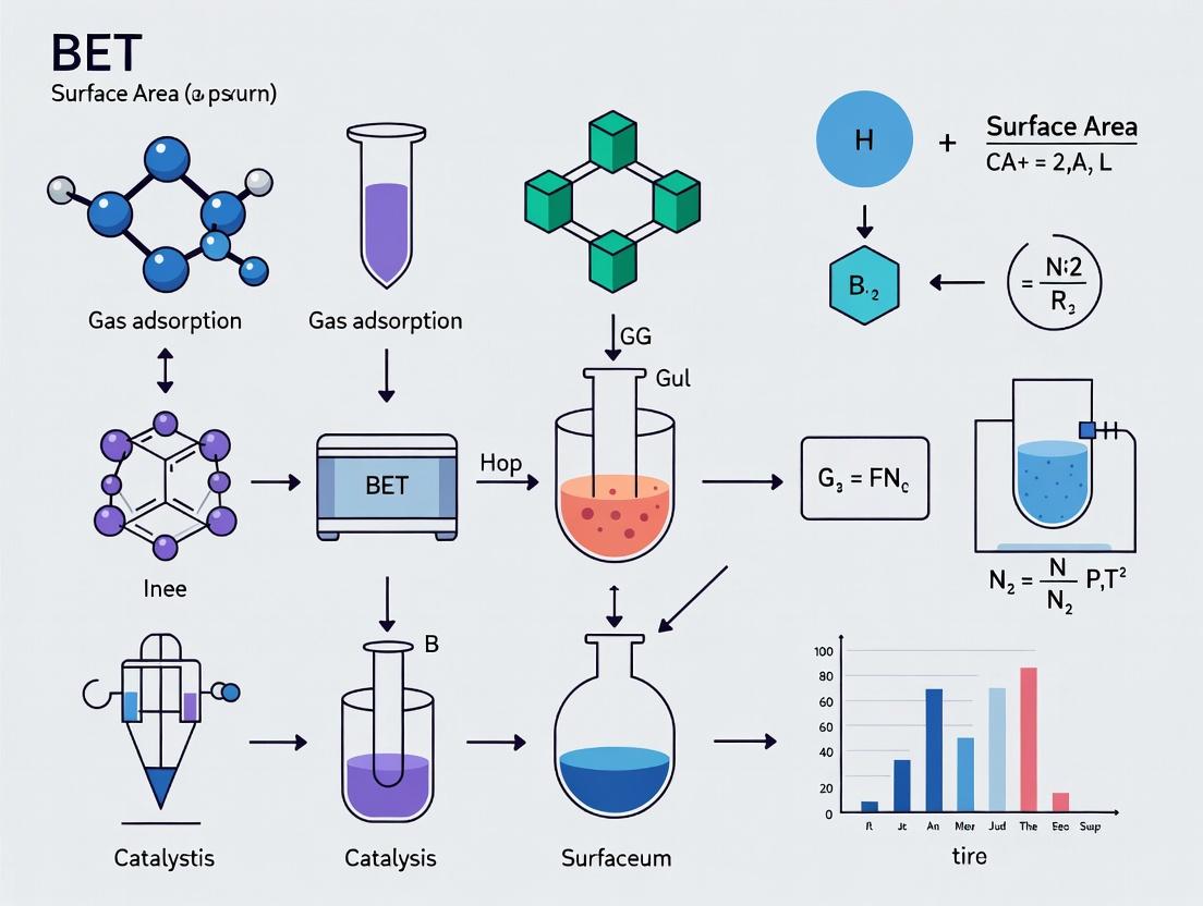
Ultimate Guide to BET Surface Area Analysis for Catalysts: Techniques, Protocols, and Advanced Applications in Pharmaceutical R&D
This comprehensive guide details the BET surface area measurement procedure for heterogeneous catalysts, a critical parameter in pharmaceutical catalyst development and drug synthesis.
Ultimate Guide to BET Surface Area Analysis for Catalysts: Techniques, Protocols, and Advanced Applications in Pharmaceutical R&D
Abstract
This comprehensive guide details the BET surface area measurement procedure for heterogeneous catalysts, a critical parameter in pharmaceutical catalyst development and drug synthesis. It explores the foundational theory of physisorption, provides a step-by-step methodology for accurate measurement, addresses common troubleshooting and optimization challenges, and covers validation protocols and comparative analysis with other characterization techniques. Tailored for researchers and drug development professionals, this article serves as a practical resource for ensuring reliable catalyst characterization in biomedical research.
Understanding BET Theory: Why Surface Area is Critical for Catalyst Performance in Drug Synthesis
Within the broader thesis on BET surface area measurement for catalysts research, the BET theory and the physisorption isotherm constitute the foundational framework. Accurate characterization of catalyst surface area is paramount, as it directly correlates with active site availability and catalytic performance. This application note details the core principles, protocols, and tools essential for reliable gas physisorption analysis.
Core Theoretical Principles
The BET Theory
The Brunauer-Emmett-Teller (BET) theory (1938) extends the Langmuir model for monolayer adsorption to multilayer physical adsorption (physisorption) on solid surfaces. Its core assumption is that multilayer adsorption can occur on a free solid surface, with the heat of adsorption for all layers beyond the first being equal to the heat of liquefaction of the adsorbate gas. The derived BET equation is used to calculate the specific surface area (SSA).
The BET Equation (Linear Form): [ \frac{1}{n(\frac{P0}{P} - 1)} = \frac{C - 1}{nm C} (\frac{P}{P0}) + \frac{1}{nm C} ] Where:
- (P) = equilibrium adsorption pressure
- (P_0) = saturation pressure of adsorbate at analysis temperature
- (n) = quantity of gas adsorbed at relative pressure (P/P_0)
- (n_m) = monolayer capacity (moles of gas required to form a complete monolayer)
- (C) = BET constant related to the net enthalpy of adsorption of the first layer
The Physisorption Isotherm
A physisorption isotherm is a plot of the quantity of non-reactive gas (e.g., N₂, Ar, Kr) adsorbed by a solid versus relative pressure ((P/P_0)) at constant temperature (typically 77 K for N₂). The isotherm's shape reveals critical textural properties. The IUPAC classifies six primary isotherm types, with Type II (non-porous/macroporous) and Type IV (mesoporous) being most common for catalysts.
Table 1: Common Adsorbate Gases for BET Surface Area Analysis
| Adsorbate Gas | Analysis Temperature | Typical Application | Pros | Cons |
|---|---|---|---|---|
| Nitrogen (N₂) | 77 K (liquid N₂ bath) | Standard SSA measurement for meso/macroporous materials | Widely accepted, high precision, abundant | Micropore diffusion issues, low pressure sensitivity |
| Argon (Ar) | 77 K or 87 K (liquid Ar bath) | Microporous materials, carbonaceous solids | Non-polar, avoids quadrupole interactions of N₂ | More expensive, requires liquid Ar |
| Krypton (Kr) | 77 K | Very low surface area materials (< 1 m²/g) | High saturation pressure, sensitive for low areas | Expensive, complex analysis |
Table 2: IUPAC Physisorption Isotherm Classification (Key Types for Catalysts)
| Type | Shape | Hysteresis Loop? | Pore Structure Indicated | Typical Catalyst Example |
|---|---|---|---|---|
| II | Sigmoidal, no plateau at high P/P₀ | No | Non-porous or macroporous (>50 nm) | Fused metal catalysts, some supports |
| IV | Sigmoidal, plateau at high P/P₀ | Yes (Type H1, H2, H3) | Mesoporous (2-50 nm) | Alumina, silica, mesoporous sieves |
| I | Rapid rise at very low P/P₀, plateau | No | Microporous (<2 nm) | Zeolites, activated carbons, MOFs |
Table 3: Common Data Reduction Models for Pore Size Distribution (PSD)
| Model | Theoretical Basis | Best For | Output |
|---|---|---|---|
| BJH (Barrett-Joyner-Halenda) | Capillary condensation in cylindrical pores | Mesopore PSD (2-50 nm) | Pore volume & size distribution |
| NLDFT / QSDFT | Statistical mechanics, molecular model | Micropore & Mesopore PSD | Most accurate PSD across range |
| t-plot / αₛ-plot | Comparison to standard isotherm | Micropore volume & external SSA | Micropore volume, external surface area |
Experimental Protocol: BET Surface Area Measurement for Catalysts
Protocol 1: Sample Preparation and Degassing
- Objective: To remove physically adsorbed contaminants (H₂O, CO₂) from the catalyst surface without altering its structure.
- Materials: BET analyzer, degas station, sample tubes, heating mantles, high-purity N₂/He gas.
- Procedure:
- Weigh an empty, clean sample tube with a stem filler rod. Record mass (Wtube).
- Add an appropriate sample mass (typically 50-200 mg for catalysts) to the tube. Record exact mass (Wtotal).
- Attach tube to the degas port of the preparation station.
- Apply heat under vacuum or a flowing inert gas (He/N₂). Critical Conditions: Temperature and time must be optimized per catalyst. A common starting point is 150-300°C for 3-12 hours under vacuum. Temperature must be below the catalyst's calcination or structural collapse temperature.
- Cool to room temperature under continuous purge/vacuum.
- Re-weigh the tube (Wfinal). Calculate the degassed sample mass: Wsample = Wfinal - Wtube.
Protocol 2: Physisorption Isotherm Measurement (N₂ at 77 K)
- Objective: To collect high-resolution adsorption and desorption data points.
- Materials: Degassed sample, BET analyzer (volumetric or gravimetric), liquid N₂ Dewar, high-purity N₂ (99.999%) and He gases.
- Procedure (Volumetric Method):
- Mount the degassed sample tube onto the analysis port of the instrument.
- Immerse the sample cell in a liquid N₂ bath (77 K) using a Dewar. Maintain constant level.
- The instrument introduces precise doses of N₂ into the sample cell and measures the equilibrium pressure.
- The quantity adsorbed is calculated from the pressure change using gas laws (e.g., ideal gas, van der Waals).
- Measure the adsorption branch by incrementally increasing (P/P0) from ~10⁻⁷ to 0.995.
- Measure the desorption branch by incrementally decreasing (P/P0) back to the starting point.
- Record a minimum of 35-50 data points per branch, with higher density in the BET range (0.05-0.30 (P/P_0)).
Protocol 3: BET Surface Area Calculation (Data Reduction)
- Objective: To determine the monolayer capacity (n_m) and calculate specific surface area.
- Procedure:
- Select the linear region of the adsorption isotherm, typically between (P/P0 = 0.05) and 0.30. Note: For microporous materials, this range may shift lower (0.005-0.1).
- Transform the raw data according to the linear BET equation.
- Plot ( \frac{P/P0}{n(1-P/P0)} ) vs. (P/P0) for the selected points.
- Perform a linear regression. The slope (s = (C-1)/(nm C)) and intercept (i = 1/(nm C)).
- Calculate monolayer capacity: (nm = 1/(s + i)).
- Calculate specific surface area: (SSA = (nm \cdot NA \cdot \sigma) / (M \cdot m)).
- (NA) = Avogadro's number (6.022×10²³ mol⁻¹)
- (\sigma) = cross-sectional area of adsorbate molecule (0.162 nm² for N₂ at 77 K)
- (M) = molar mass of adsorbate (for N₂, 28.0134 g/mol)
- (m) = mass of sample (g)
Visualization: BET Analysis Workflow
Diagram Title: BET Surface Area Analysis Workflow for Catalysts
The Scientist's Toolkit: Key Research Reagent Solutions
Table 4: Essential Materials for BET Analysis of Catalysts
| Item | Function & Importance in Catalysis Research | Typical Specification |
|---|---|---|
| High-Purity N₂ Gas | Primary adsorbate for standard SSA measurement. Impurities (H₂O, hydrocarbons) skew results by blocking sites. | 99.999% (5.0 grade) or better, with inline filters. |
| High-Purity He Gas | Used for dead volume calibration (pynometry) and as a purge gas during degassing. Must be inert. | 99.999% (5.0 grade). |
| Liquid Nitrogen | Cryogen to maintain analysis temperature at 77 K. Consistency of bath level is critical for data stability. | Industrial grade, from a reliable supplier. |
| Sample Tubes | Hold the catalyst during analysis. Must be chemically inert and withstand vacuum/temperature cycles. | Borosilicate glass or quartz, with calibrated free space. |
| Reference Material | Certified standard used to validate instrument performance and operator technique. | NIST-traceable (e.g., alumina, silica). |
| Microporous Reference | For validating micropore analysis. | Zeolite (e.g., HZSM-5) or carbon black with certified microporous area. |
| Degassing Station | Prepares catalyst surface by removing contaminants without sintering or reducing the active phase. | Capable of controlled heating (up to 400°C) under vacuum or inert flow. |
Within the broader thesis on BET (Brunauer-Emmett-Teller) surface area measurement for catalysts research, this article details its critical application in pharmaceutical catalysis. The BET method provides the foundational quantitative metric—specific surface area (m²/g)—that directly correlates with catalytic performance parameters: activity, selectivity, and yield. For API (Active Pharmaceutical Ingredient) synthesis, where efficient, selective, and scalable reactions are paramount, optimizing catalyst surface area is a primary design strategy.
Application Notes: The Surface Area-Catalysis Relationship
Catalytic Activity
Activity, often measured by Turnover Frequency (TOF), is intrinsically linked to the number of accessible active sites. Higher BET surface area generally increases active site availability, enhancing reaction rate.
Table 1: Impact of Pd/C Catalyst Surface Area on Hydrogenation Activity
| Catalyst | BET Surface Area (m²/g) | TOF for Nitroarene Reduction (h⁻¹) | Reference Year |
|---|---|---|---|
| Pd/C (Low SA) | 580 | 1,200 | 2023 |
| Pd/C (Medium SA) | 950 | 2,150 | 2023 |
| Pd/C (High SA) | 1,450 | 3,800 | 2023 |
| Mesoporous Pd/SiO₂ | 1,210 | 4,500 | 2024 |
Key Insight: While TOF typically increases with surface area, pore structure and metal dispersion (derived from BJH and t-plot analysis of BET data) are co-determinants. Micropores (<2 nm) may limit substrate access in pharmaceutical reactions involving bulky intermediates.
Selectivity
Selectivity in multi-pathway reactions is governed by the preferential adsorption and orientation of reactants on the catalyst surface. Tuned surface area and pore geometry can sterically and electronically influence this.
Table 2: Selectivity Control in Suzuki-Miyaura Coupling via Surface Engineering
| Catalyst Type | Avg. Pore Width (nm) | BET SA (m²/g) | Selectivity for Biaryl Isomer A:B | Notes |
|---|---|---|---|---|
| Pd/Activated Carbon | 2.1 | 1,100 | 65:35 | Micropores favor smaller isomer |
| Pd on Ordered Mesoporous Carbon | 6.5 | 780 | 23:77 | Mesopores favor bulkier isomer |
| Pd on Wide-Pore SiO₂ | 12.0 | 320 | 5:95 | High steric differentiation |
Application Note: For chiral pharmaceutical synthesis, immobilizing chiral ligands on high-surface-area supports (e.g., silica >300 m²/g) increases enantioselective site density, improving enantiomeric excess (e.e.).
Reaction Yield
Yield is the product of activity and selectivity over time. An optimal, not necessarily maximal, surface area prevents side reactions (e.g., over-hydrogenation, decomposition) and catalyst deactivation via coking.
Table 3: Yield Optimization in Reductive Amination Using Ni Catalysts
| Catalyst Form | BET SA (m²/g) | Pore Volume (cm³/g) | Max Yield (%) | Key Limitation |
|---|---|---|---|---|
| Ni Nanopowder | 35 | 0.05 | 72 | Sintering, leaching |
| Ni on Al₂O₃ (High SA) | 245 | 0.75 | 88 | Minor byproduct formation |
| Ni on Al₂O₃ (Moderate SA) | 155 | 0.48 | 96 | Optimal mass transfer |
| Hierarchical Ni-Zeolite | 520 | 0.30 | 81 | Substrate trapping |
Experimental Protocols
Protocol: Correlating Pd/C Catalyst BET Surface Area with Hydrogenation Performance
Aim: To measure the BET surface area of commercial Pd/C catalysts and correlate it with their activity/selectivity in the hydrogenation of a pharmaceutical nitro-precursor.
Materials: See "Scientist's Toolkit" below.
Procedure:
- Catalyst Pre-treatment (Degassing):
- Weigh ~0.15 g of each Pd/C catalyst into a clean BET sample tube.
- Seal tube with a transducer frit. Attach to the degas port of a surface area analyzer (e.g., Micromeritics 3Flex).
- Heat to 150 °C under vacuum (or flowing N₂) for a minimum of 6 hours to remove physisorbed contaminants. Note: Temperature may be lowered for thermally sensitive materials.
BET Surface Area Measurement (N₂ Physisorption at 77 K):
- After cooling, transfer the sample tube to the analysis port.
- Immerse the tube in a liquid N₂ bath (77 K).
- The instrument automatically admits precise doses of N₂ gas and measures the equilibrium pressure to construct an adsorption isotherm.
- Collect data in the relative pressure (P/P₀) range of 0.05 to 0.30.
- Use the instrument software to apply the BET equation to this linear region, calculating the specific surface area (m²/g). Report the correlation coefficient (R² > 0.999 is ideal).
Catalytic Hydrogenation Test:
- In a parallel set-up, charge a 50 mL hydrogenation vessel with the pharmaceutical nitro-precursor (1.0 mmol), catalyst (2 mol% Pd basis), and methanol (10 mL).
- Purge the vessel three times with H₂ (1 atm).
- Stir the reaction vigorously at 25 °C under 1 atm H₂.
- Monitor reaction progress by TLC or HPLC every 30 minutes.
- Upon completion or at 4 hours, filter the reaction mixture through a Celite pad to remove the catalyst.
- Analyze the filtrate by quantitative HPLC to determine conversion (%) and yield (%) of the desired amine product.
Data Correlation:
- Plot TOF (mol product / (mol Pd * h)) and reaction yield against the measured BET surface area.
- Perform product purity analysis (e.g., HPLC-MS) to assess selectivity changes.
Protocol: Designing a Selective Oxidation Catalyst via Surface Area/Pore Size Optimization
Aim: To synthesize and characterize a series of mesoporous TiO₂ supports with varying pore sizes, load with Au nanoparticles, and test in the selective oxidation of a steroidal substrate.
Procedure:
- Support Synthesis (Evaporation-Induced Self-Assembly):
- Prepare a homogeneous solution of titanium(IV) isopropoxide, Pluronic P123 template, ethanol, and HCl.
- Age the solution at 40°C for 24h, then evaporate ethanol at 60°C.
- Calcine three separate batches at 350°C, 450°C, and 550°C to generate materials with increasing average pore size.
Full Material Characterization:
- Perform N₂ physisorption (77 K) on all three TiO₂ supports and subsequent Au/TiO₂ catalysts.
- Obtain BET surface area, BJH pore size distribution, and total pore volume.
- Confirm Au loading (~1 wt%) via ICP-OES and nanoparticle size (<5 nm) via TEM.
Selective Oxidation Test:
- React the steroidal alcohol (0.5 mmol) with catalyst (1 mol% Au) in toluene under O₂ (1 atm) at 80°C.
- Analyze time-point samples by HPLC to track the formation of the target ketone versus over-oxidation byproducts (e.g., carboxylic acids).
Visualization: Workflows and Relationships
Diagram 1: Catalyst R&D Feedback Loop (79 chars)
Diagram 2: How Surface Area Drives Catalytic Performance (67 chars)
The Scientist's Toolkit: Key Research Reagents & Materials
Table 4: Essential Materials for Surface Area-Optimized Catalysis Research
| Item | Function/Benefit in Research |
|---|---|
| Reference Catalysts (e.g., NIST-certified SiO₂, Al₂O₃) | Calibration and validation of BET surface area analyzers. |
| Mesoporous Silica Supports (SBA-15, MCM-41) | Tunable, high-surface-area (>500 m²/g) model supports for mechanistic studies. |
| Metal Precursors (e.g., Pd(NO₃)₂, H₂PtCl₆, HAuCl₄) | For precise wet impregnation to create well-dispersed active sites. |
| Pharmaceutical-Relevant Test Substrates (e.g., nitroarenes, protected amino acids, steroidal ketones) | Relevant probe molecules for testing activity/selectivity under pharma-like conditions. |
| High-Purity Gases (N₂, 99.999% for BET; H₂, O₂ for reactions) | Essential for accurate physisorption measurements and reproducible catalytic tests. |
| Micromeritics or Quantachrome Sample Tubes | Specialized glassware designed for precise degassing and analysis on commercial BET systems. |
| Static/Dynamic Chemisorption Kit | Optional add-on to BET analyzer for quantifying active site density via gas titration (e.g., CO, H₂). |
Within catalyst research for pharmaceutical synthesis, the Brunauer-Emmett-Teller (BET) surface area measurement procedure is a cornerstone analytical technique. It is indispensable for characterizing porous materials that serve as catalysts or supports in drug intermediate synthesis. The fundamental distinction between microporous (pores < 2 nm) and mesoporous (pores 2–50 nm) materials, as defined by IUPAC, critically determines their adsorption capacity, diffusion kinetics, and catalytic selectivity. Accurate BET analysis directly informs the selection of the optimal porous material for a given synthetic transformation, impacting yield, purity, and scalability of drug intermediates.
Definitions, Properties, and Quantitative Comparison
Microporous Materials: Feature pore diameters less than 2 nanometers. The confined space induces strong adsorption potentials, making them excellent for small molecule separations and acid-catalyzed reactions requiring shape selectivity (e.g., zeolites, certain activated carbons).
Mesoporous Materials: Feature pore diameters between 2 and 50 nanometers. Their larger channels facilitate faster diffusion of bulkier molecules and reduce pore-blocking, making them ideal for immobilizing large organocatalysts or metal complexes (e.g., MCM-41, SBA-15, mesoporous aluminosilicates).
Table 1: Comparative Properties of Microporous and Mesoporous Materials
| Property | Microporous Materials | Mesoporous Materials |
|---|---|---|
| Pore Width (IUPAC) | < 2 nm | 2 – 50 nm |
| Typical BET Surface Area | Very High (500 – 1500 m²/g) | High (200 – 1000 m²/g) |
| Primary Adsorption Mechanism | Micropore Filling | Multilayer Adsorption |
| Dominant Diffusion Type | Configurational/Activated | Knudsen/Surface |
| Typical Catalyst Loading Capacity | Low (≤ 5 wt%) | Moderate to High (5 – 30 wt%) |
| Ideal for Molecule Size | Small (< 1 nm) Drug Intermediates | Bulky, Functionalized Intermediates |
| Common Examples | Zeolite (ZSM-5, HY), Activated Carbon | MCM-41, SBA-15, KIT-6 |
Impact on Drug Intermediate Synthesis: Application Notes
- Selective Alkylation (Microporous Advantage): Zeolites like ZSM-5 use shape selectivity to perform regioselective Friedel-Crafts alkylation, yielding the desired para-isomer of a drug intermediate while excluding ortho/meta isomers due to spatial constraints in micropores.
- Cross-Coupling Reactions (Mesoporous Advantage): Mesoporous SBA-15 functionalized with palladium complexes provides ample space for bulky phosphine ligands and reactants, enabling efficient Suzuki-Miyaura coupling of aryl halides with boronic acids to form biaryl intermediates.
- Chiral Synthesis: Mesoporous materials can be grafted with chiral organocatalysts (e.g., proline derivatives). Their open structure allows for the diffusion and asymmetric transformation of prochiral ketones into valuable chiral alcohol intermediates.
- Tandem/Cascade Reactions: Multifunctional catalysts, where acidic sites (in micropores) and metal sites (in mesopores) work in concert, can synthesize complex intermediates in one pot, improving atom economy.
Experimental Protocols
Protocol 4.1: BET Surface Area and Pore Size Analysis for Catalyst Screening
Objective: To determine the BET surface area, pore volume, and pore size distribution of a candidate porous material for catalyst support.
Materials: See "The Scientist's Toolkit" below.
Procedure:
- Sample Preparation (~6-8 hours): Weigh 100-200 mg of sample into a pre-tared analysis tube. Degas the sample under vacuum at 300°C (or a temperature relevant to the material's stability) for 6 hours to remove physisorbed contaminants.
- Analysis Setup: Mount the degassed tube on the analysis port of a volumetric gas sorption analyzer (e.g., Micromeritics, Anton Paar). Immerse the sample tube in a liquid nitrogen (77 K) Dewar flask.
- Data Acquisition: Under controlled dosing, measure the volume of nitrogen gas adsorbed and desorbed at relative pressures (P/P₀) from 0.01 to 0.99.
- Data Analysis:
- Apply the BET equation to the adsorption data in the relative pressure range 0.05–0.30 to calculate the specific surface area.
- Use the Barrett-Joyner-Halenda (BJH) method on the desorption isotherm branch to calculate mesopore size distribution and volume.
- Apply the t-plot or Horvath-Kawazoe method to determine micropore volume and surface area.
- Interpretation: Correlate high micropore volume with shape-selective potential. Correlate defined mesopore peaks in the 2-10 nm range with suitability for functionalization with bulky catalytic species.
Protocol 4.2: Immobilization of a Palladium Catalyst on SBA-15 for Cross-Coupling
Objective: To synthesize a heterogeneous Pd catalyst supported on mesoporous silica SBA-15 for use in Suzuki-Miyaura coupling.
Procedure:
- Support Activation (3 hours): Dry 1.0 g of SBA-15 at 150°C under vacuum for 2 hours to remove moisture. Transfer to dry toluene (20 mL) under inert atmosphere (N₂/Ar).
- Functionalization with Aminosilane (24 hours): Add 1.2 mmol of 3-aminopropyltriethoxysilane (APTES) to the suspension. Reflux at 110°C for 20 hours. Cool, filter, and wash thoroughly with toluene, ethanol, and diethyl ether. Dry to obtain NH₂-SBA-15.
- Metal Complex Grafting (18 hours): Suspend NH₂-SBA-15 in dry dichloromethane (15 mL). Add 0.2 mmol of Palladium(II) acetate. Stir at room temperature for 16 hours. Filter, wash with DCM, and dry under vacuum to yield Pd/NH₂-SBA-15.
- Catalyst Evaluation: Use the prepared catalyst (e.g., 2 mol% Pd) in a model Suzuki reaction between 4-bromoanisole and phenylboronic acid. Monitor conversion via HPLC or GC-MS.
Visualizations
Diagram 1: BET Analysis Guides Catalyst Selection
Diagram 2: Reaction in a Mesoporous Catalyst
The Scientist's Toolkit
Table 2: Essential Research Reagents and Materials
| Item | Function in Research |
|---|---|
| Zeolite (e.g., H-BEA, ZSM-5) | Prototypical microporous solid acid catalyst for alkylation, isomerization. |
| Mesoporous Silica (e.g., SBA-15) | High-surface-area support with tunable mesopores for catalyst immobilization. |
| 3-Aminopropyltriethoxysilane (APTES) | Coupling agent for functionalizing silica surfaces with amine groups. |
| Palladium(II) Acetate | Common Pd precursor for synthesizing supported heterogeneous catalysts. |
| Liquid Nitrogen (77 K) | Coolant required for standard N₂ physisorption BET surface area analysis. |
| Quantachrome or Micromeritics Analyzer | Instrument for performing automated gas sorption measurements. |
| Tube Reactor with Temperature Control | For evaluating catalytic performance in model drug intermediate syntheses. |
| Inline GC-MS or HPLC | For real-time monitoring of reaction conversion and selectivity. |
Within the critical research field of catalyst development, the precise measurement of specific surface area, pore size, and pore volume is fundamental. The Brunauer-Emmett-Teller (BET) theory provides the standard methodology for determining the specific surface area of porous materials. The accuracy and reliability of BET surface area measurements are intrinsically linked to the performance of the analytical instrument used. This application note, framed within a broader thesis on BET procedures for catalyst research, provides an overview of the two principal classes of modern gas sorption analyzers: volumetric and gravimetric. We detail their operating principles, comparative performance, and provide standardized protocols for catalyst characterization.
Core Principles & Equipment Comparison
Gas sorption analyzers measure the quantity of a gas (typically N₂ at 77 K) adsorbed onto or desorbed from a solid surface at equilibrium vapor pressure. The two methodologies differ in how they quantify this gas amount.
Volumetric (Manometric) Method: This approach calculates the amount of gas adsorbed by precisely measuring pressure changes within a calibrated, fixed-volume manifold. The sample is held at constant temperature (e.g., liquid nitrogen bath), and known doses of adsorbate gas are introduced. The quantity adsorbed is determined from the pressure difference before and after adsorption, using the gas laws.
Gravimetric Method: This method directly measures the increase in mass of the sample during gas exposure using a highly sensitive microbalance. The sample hangs from the balance within a controlled environment, and the mass change is recorded as a function of relative pressure.
The following table summarizes the key quantitative and qualitative differences between modern implementations of these systems.
Table 1: Comparison of Modern Volumetric vs. Gravimetric Gas Sorption Analyzers
| Feature | Volumetric Analyzers | Gravimetric Analyzers |
|---|---|---|
| Measurement Principle | Manometric; measures pressure/volume change. | Direct mass change via microbalance. |
| Typical Balance Sensitivity | Not Applicable (N/A) | ≤ 0.1 µg |
| Sample Mass Range | 50 mg – 5 g (recommended) | 1 mg – 1 g (recommended) |
| Key Advantage | High accuracy for high-surface-area materials; robust, common for BET. | Direct measurement; allows for simultaneous thermal analysis (STA); ideal for in-situ conditioning studies. |
| Key Limitation | Requires buoyancy/dead volume correction. More complex for low-surface-area samples. | More sensitive to vibrations and thermal gradients. Buoyancy effects must be carefully accounted for. |
| Optimal Use Case | Routine, high-throughput BET surface area and pore analysis of catalysts. | Studies involving mass change during in-situ activation, chemisorption, or high-pressure/vapor sorption. |
| Typical Relative Cost | Moderate to High | High |
Experimental Protocols
Protocol 3.1: Standard BET Surface Area Analysis of a Heterogeneous Catalyst (Volumetric Method)
Objective: To determine the specific surface area of a mesoporous γ-alumina catalyst using N₂ adsorption at 77 K via a volumetric analyzer.
Research Reagent Solutions & Materials:
- Sample: 150-200 mg of γ-alumina catalyst.
- Adsorptive Gas: High-purity Nitrogen (N₂, 99.999%) and Helium (He, 99.999%).
- Analysis Tube: A precisely sized, calibrated glass or metal tube with a sealable connector.
- Coolant: Liquid nitrogen in a dedicated Dewar flask.
- Degassing Station: A separate or integrated unit for sample preparation.
Procedure:
- Sample Preparation: Accurately weigh an empty, clean analysis tube. Add the catalyst sample and re-weigh to determine sample mass. Attach tube to the degassing station.
- Sample Degassing: Activate the sample by heating under vacuum (e.g., 150°C for alumina) or inert gas flow for a minimum of 6 hours to remove physisorbed water and contaminants. Cool to room temperature.
- Dead Volume Calibration: Transfer the sealed analysis tube to the analysis port of the volumetric analyzer. Perform a free-space (dead volume) measurement using Helium gas, as it is not adsorbed under typical conditions. This calibrates the system volume not occupied by the sample.
- Adsorption Isotherm: Immerse the sample cell in a liquid nitrogen bath (77 K). The instrument automatically introduces incremental doses of N₂ gas. After each dose, the system monitors pressure until equilibrium is reached, then records the quantity adsorbed. This continues up to a relative pressure (P/P₀) of ~0.99.
- Desorption Isotherm: The process is reversed by withdrawing gas doses to record the desorption branch.
- Data Analysis: The software collects the adsorption data. The linear region of the BET transformation (typically P/P₀ between 0.05 and 0.30) is selected to calculate the monolayer capacity (Vm) and subsequently the specific surface area.
Protocol 3.2:In-SituActivation and BET Measurement (Gravimetric Method)
Objective: To monitor mass loss during thermal activation of a metal-organic framework (MOF) catalyst precursor and subsequently measure its N₂ sorption isotherm.
Research Reagent Solutions & Materials:
- Sample: 20-50 mg of as-synthesized MOF powder.
- Adsorptive Gas: High-purity Nitrogen (N₂, 99.999%).
- Purge Gas: High-purity Helium (He, 99.999%) or Argon.
- Sample Basket: A lightweight, inert metal (stainless steel or platinum) basket suspended from the microbalance.
- Coolant: Liquid nitrogen Dewar with automatic level control.
Procedure:
- System Setup: Tare the microbalance with the empty sample basket installed. Carefully load the MOF sample into the basket.
- In-Situ Activation: Under a continuous flow of inert purge gas, program a controlled temperature ramp (e.g., 2°C/min to 200°C) and hold for 12 hours. The microbalance continuously records the mass loss due to solvent and ligand removal.
- Buoyancy Correction: After cooling to analysis temperature (e.g., 30°C), perform a buoyancy correction scan using He gas across a pressure range.
- Sorption Isotherm: Set the sample temperature to 77 K using a liquid nitrogen bath. The system introduces controlled doses of N₂, and the microbalance directly records the equilibrium mass gain at each relative pressure step, constructing the full adsorption and desorption isotherm.
- Analysis: The software corrects for buoyancy effects and calculates the BET surface area from the adsorption data.
Visualized Workflows
Volumetric BET Analysis Workflow
Gravimetric In-Situ Activation & BET Workflow
The Scientist's Toolkit: Essential Research Materials
Table 2: Key Reagents and Materials for Gas Sorption Analysis
| Item | Function & Importance |
|---|---|
| High-Purity Nitrogen (N₂, 99.999%) | The standard adsorptive gas for BET surface area analysis (cross-sectional area of 0.162 nm²). Purity is critical to prevent contamination of the sample and analyzer. |
| High-Purity Helium (He, 99.999%) | Used for dead-volume calibration in volumetric systems and for buoyancy correction in gravimetric systems due to its non-adsorbing nature. |
| Liquid Nitrogen (LN₂) | Provides the constant 77 K temperature bath required for standard N₂ physisorption experiments. Consistent level control is vital for data quality. |
| Analysis Tubes (Volumetric) | Calibrated, sample-specific cells of known volume. Must be meticulously cleaned and dried between uses to prevent cross-contamination. |
| Sample Baskets (Gravimetric) | Ultra-lightweight, inert containers (e.g., platinum) that hold the sample in the microbalance. Must be stable at high activation temperatures. |
| Micromeritics ASAP 2460, Quantachrome Autosorb, 3Flex | Examples of modern, automated volumetric analyzers offering high-throughput and advanced data analysis for catalyst characterization. |
| Rubotherm IsoSORP, Hiden Isochema IGA | Examples of modern gravimetric analyzers offering coupled thermogravimetry and precise vapor/gas sorption capabilities. |
| Degassing Station | A separate or integrated unit for sample preparation under controlled temperature and vacuum/inert flow, essential for removing adsorbed species. |
Step-by-Step BET Protocol: From Sample Prep to Data Acquisition for Catalyst R&D
Within the framework of BET (Brunauer-Emmett-Teller) surface area analysis for catalysts, the accuracy and reproducibility of measurements are fundamentally dependent on the quality of sample pre-treatment. The process of outgassing, or degassing, is a critical pre-analytical step designed to remove physisorbed and chemisorbed contaminants (e.g., water vapor, atmospheric gases, hydrocarbons) from the catalyst surface and pores. Proper activation not only ensures a clean, reproducible surface but can also activate catalytic sites. Inadequate outgassing leads to significant underestimation of surface area, pore volume, and erroneous pore size distribution.
The Role of Outgassing in BET Analysis
Outgassing prepares the catalyst sample for analysis by creating a clean, dry, and stable surface. The BET theory assumes gas adsorption occurs on a free surface; residual contaminants block adsorption sites, leading to invalid isotherms. The procedure must be tailored to the catalyst's composition, thermal stability, and intended application state.
Key Outgassing Parameters and Quantitative Data
Optimal outgassing conditions vary based on material properties. The table below summarizes standard and material-specific protocols.
Table 1: Standard Outgassing Parameters for Common Catalyst Types
| Catalyst Type | Typical Temperature Range (°C) | Typical Time (hours) | Vacuum Level (Torr) | Primary Contaminants Removed | Special Considerations |
|---|---|---|---|---|---|
| Metal Oxides (e.g., Al2O3, SiO2) | 150 - 300 | 3 - 12 | <10^-2 | H2O, CO2, organics | Avoid sintering; T < Tammann temp. |
| Zeolites & Molecular Sieves | 300 - 400 | 8 - 15 | <10^-3 | H2O, volatile organics | Slow ramp to preserve structure. |
| Activated Carbon | 200 - 300 | 4 - 8 | <10^-3 | H2O, adsorbed VOCs | Risk of combustion if O2 present; use inert purge. |
| Supported Metals (e.g., Pt/Al2O3) | 200 - 250 (inert) | 3 - 6 | <10^-2 | H2O, atmospheric gases | May require in-situ reduction post-outgas. |
| Sulfided Catalysts (e.g., CoMo-S) | 150 - 200 | 4 - 8 | <10^-2 | H2O, light hydrocarbons | Higher temps may alter sulfided phase. |
| Temperature-Sensitive Organometallics | Ambient - 80 | 6 - 24 | <10^-2 | Solvents, light gases | Use dynamic vacuum with gentle heating. |
Table 2: Effects of Inadequate Outgassing on BET Results for γ-Al2O3
| Outgassing Condition | Measured BET Surface Area (m²/g) | Error vs. Optimal Protocol | Pore Volume (cm³/g) |
|---|---|---|---|
| Optimal: 250°C, 10 hr, <10^-3 Torr | 215 ± 5 | Baseline | 0.48 |
| Insufficient Temp: 100°C, 10 hr | 185 ± 10 | -14% | 0.41 |
| Insufficient Time: 250°C, 1 hr | 198 ± 8 | -8% | 0.44 |
| No Vacuum (Flow N2): 250°C, 10 hr | 205 ± 6 | -5% | 0.46 |
Detailed Experimental Protocols
Protocol 1: Standard Vacuum Outgassing for Metal Oxide Catalysts
This protocol is suitable for thermally stable oxides like alumina, silica, and titania prior to BET analysis.
Materials & Equipment:
- High-vacuum degassing system (e.g., Micromeritics Smart VacPrep, or custom glass manifold).
- Sample tubes with sealed stem and fitted with a removable glass bulb.
- Furnace or heating mantle with precise temperature control (±1°C).
- Vacuum gauge capable of reading down to 10^-4 Torr.
- Liquid nitrogen trap (cold finger).
- High-purity (99.999%) dry nitrogen gas for backfilling.
Procedure:
- Sample Loading: Accurately weigh (to 0.01 mg) an appropriate sample mass (typically 50-200 mg) into a clean, pre-weighed sample tube. The mass should yield a total surface area for analysis between 5-200 m².
- Initial Evacuation: Attach the tube to the degassing station. Apply a slow vacuum to prevent powder entrainment. Reach a rough vacuum of ~10^-1 Torr at room temperature and hold for 15 minutes.
- Heating Ramp: Begin heating the sample at a controlled rate of 5-10°C per minute until the target temperature (e.g., 250°C for γ-Al2O3) is reached.
- Isothermal Hold: Maintain the target temperature under dynamic vacuum (<10^-2 Torr, ideally <10^-3 Torr) for a minimum of 6 hours. For microporous materials, extend to 12+ hours.
- Cool Down: After the hold time, shut off the heater. Allow the sample to cool under continuous dynamic vacuum to below 50°C. This prevents re-adsorption of contaminants.
- Backfill and Isolation: Isolate the sample tube from the vacuum manifold by closing its stopcock. Carefully backfill the tube with dry, inert gas (N2 or Ar) to atmospheric pressure.
- Final Weighing: Immediately weigh the tube to determine the degassed sample mass. The sample is now ready for BET analysis.
Protocol 2:In-SituReduction-Activation for Supported Metal Catalysts
For catalysts requiring activation of the metal phase (e.g., Pt/SiO2, Ni/Al2O3), outgassing is combined with chemical reduction.
Procedure:
- Primary Outgas: Follow Protocol 1 steps 1-5 using an inert temperature (e.g., 200°C) to remove physisorbed species.
- Gas Switching: While the sample is still under vacuum and at temperature, isolate the system. Introduce ultra-high purity hydrogen (H2) gas to a pressure of 100-500 Torr.
- Reduction Step: Maintain the sample in static or slowly flowing H2 atmosphere at the reduction temperature (varies by metal; e.g., 350°C for Ni, 250°C for Pt) for 1-4 hours.
- Secondary Outgas: Re-evacuate the system to high vacuum (<10^-3 Torr) at the reduction temperature to remove chemisorbed hydrogen and any produced water. Hold for 1-2 hours.
- Cool and Isolate: Cool the sample to analysis temperature (e.g., liquid N2 temperature for BET) under continuous dynamic vacuum. Isolate and weigh.
Visualization of Workflows
Standard Vacuum Outgassing Workflow
In-Situ Reduction-Activation Workflow
The Scientist's Toolkit: Essential Research Reagent Solutions & Materials
Table 3: Key Materials for Outgassing and Catalyst Pre-Treatment
| Item | Function & Rationale |
|---|---|
| High-Vacuum Degas Station | Provides controlled heating and high vacuum (<10^-3 Torr) for contaminant desorption and removal. Essential for microporous materials. |
| Sample Tubes with Sealable Stems | Hold catalyst sample; must withstand high vacuum and temperature. Fused quartz is ideal for high temperatures. |
| Liquid Nitrogen Cold Trap | Placed between sample and vacuum pump to condense volatile contaminants (water, oils), protecting the pump and improving vacuum quality. |
| Ultra-High Purity (UHP) Gases | UHP N₂, Ar (99.999%) for backfilling; UHP H₂ (99.999%) or CO for in-situ reduction/carburization. Minimizes re-contamination. |
| Temperature-Controlled Furnace | Provides precise, uniform heating (±1°C) to the sample zone. Programmable ramp rates are critical for sensitive materials. |
| Microbalance (0.01 mg resolution) | For accurate measurement of degassed sample mass, which is critical for all subsequent surface area calculations. |
| Chemically Inert Frits | Often integrated into sample tubes to hold powder in place while allowing gas flow. Must be non-adsorptive. |
| Porosity Standards | Certified reference materials (e.g., NIST alumina) with known surface area. Used to validate the entire outgassing and analysis procedure. |
The outgassing procedure is a non-negotiable, foundational step in reliable BET surface area characterization of catalysts. A one-size-fits-all approach is insufficient. The protocol must be meticulously optimized for the catalyst's composition, texture, and thermal stability, balancing contaminant removal against structural alteration. Adherence to detailed, material-specific protocols—such as those outlined here—ensures the generation of accurate, reproducible surface area data, forming a solid basis for credible structure-activity relationships in catalysis research and development.
Within the comprehensive framework of a thesis on BET surface area measurement procedures for catalyst research, the selection of an appropriate adsorbate gas is a foundational decision. This choice directly impacts measurement accuracy, reproducibility, and applicability to the material's intended function. While nitrogen (N₂) adsorption at 77 K remains the standard, krypton (Kr) and argon (Ar) are critical alternatives for low-surface-area materials and microporous characterization. This application note details the scientific rationale, comparative data, and standardized protocols for their use, tailored for researchers and scientists in catalysis and pharmaceutical development.
The Scientist's Toolkit: Essential Reagents & Materials
| Item | Function & Rationale |
|---|---|
| High-Purity N₂ Gas (≥99.999%) | Primary adsorbate for most measurements (0.1-1000 m²/g). Its quadrupole moment interacts well with most surfaces, and 77 K provides a convenient isotherm. |
| High-Purity Kr Gas (≥99.995%) | Adsorbate for very low surface areas (< 1 m²/g). Its low saturation pressure (P₀) at 77 K enhances measurement sensitivity in the relative pressure (P/P₀) range. |
| High-Purity Ar Gas (≥99.999%) | Alternative adsorbate, often at 87 K (Ar boiling point). Lacks a quadrupole moment, making it more inert for studying surface chemistry or for carbonaceous materials. |
| Ultra-High Purity He Gas | Used for dead volume calibration and purging. Non-adsorbing under analysis conditions. |
| Liquid Nitrogen (LN₂) | Cryogen for maintaining a constant 77 K bath for N₂ and Kr analysis. Requires a dewar with stable level control. |
| Liquid Argon | Cryogen for maintaining 87 K bath for Ar analysis. Provides a different temperature for probing micropores. |
| Reference Material (e.g., Alumina, Carbon Black) | Certified for BET surface area. Used for instrument validation and cross-adsorbate method calibration. |
| Sample Cells (of known volume) | For containing the degassed catalyst sample. Must be meticulously cleaned to avoid contamination. |
| Micropore Reference Material | Such as a zeolite with well-defined micropore size, for validating ultramicropore analysis with Ar at 87 K. |
Quantitative Comparison of Key Adsorbates
Table 1: Fundamental Properties of Common BET Adsorbates
| Property | Nitrogen (N₂) | Krypton (Kr) | Argon (Ar) |
|---|---|---|---|
| Standard Analysis Temperature | 77 K (LN₂) | 77 K (LN₂) | 87 K (LAr) |
| Cross-sectional Area (Ų/molecule) | 16.2 (common value) | 20.2 (common value) | 14.2 (common value) |
| Saturation Pressure (P₀) at T | ~760 Torr | ~1.6 Torr | ~250 Torr |
| Molecular Interaction | Quadrupole moment | Primarily van der Waals | No quadrupole, spherical |
| Typical Surface Area Range | 0.5 - 1000+ m²/g | 0.001 - 5 m²/g | 0.1 - 1000+ m²/g |
| Key Application | General-purpose, mesoporous materials | Very low surface area solids (e.g., dense catalysts, metals) | Micropore analysis, carbon characterization |
Table 2: Protocol Selection Guide Based on Catalyst Properties
| Catalyst Characteristic | Recommended Adsorbate | Primary Rationale | Critical Consideration |
|---|---|---|---|
| High Surface Area (> 10 m²/g) | N₂ at 77 K | Robust, standardized, vast comparative databases. | May underestimate ultramicropores. |
| Very Low Surface Area (< 1 m²/g) | Kr at 77 K | Low P₀ magnifies the measurable uptake in the BET range. | Requires precise pressure measurement. Cross-sectional area uncertainty. |
| Microporous (Zeolites, MOFs, Activated Carbons) | Ar at 87 K | Avoids N₂ quadrupole-specific interactions, yields more reliable pore size distributions in ultramicropores. | Requires liquid argon. 87 K temperature control is critical. |
| Hydrophilic / Ionic Surfaces | N₂ at 77 K or Ar at 87 K | N₂ quadrupole interacts with surface ions/molecules. Ar provides a simpler interaction for comparison. | Sample degassing is critical to remove water. |
| Chemically Inert (e.g., Carbon) | Ar at 87 K | Non-specific interaction avoids potential artifacts from N₂ quadrupole moment. | Growing standard for advanced carbon characterization. |
Experimental Protocols
Protocol 1: Standard BET Surface Area Measurement using N₂ at 77 K
This is the core protocol for the majority of catalyst samples.
I. Pre-Measurement: Sample Preparation & Degassing
- Weighing: Accurately weigh a clean, dry sample cell. Add sufficient catalyst sample to achieve a total surface area between 20-100 m² (e.g., ~100 mg of a 200 m²/g catalyst). Record the exact sample mass.
- Degassing: Secure the cell to a degas port. Apply heat (typically 150-300°C for catalysts, under vacuum or flowing inert gas) for a minimum of 3 hours (often 6-12 hours overnight). The temperature and time must be sufficient to remove all physisorbed contaminants (water, CO₂) without altering the catalyst structure.
- Cooling & Isolation: After degassing, cool the sample to near ambient temperature under continued vacuum or inert flow. Isolate and seal the sample cell.
II. Measurement: Physisorption Analysis
- Installation: Transfer the sealed sample cell to the analysis station of the physisorption instrument. The instrument manifold should be evacuated.
- Thermal Equilibrium: Immerse the sample cell in a liquid nitrogen (LN₂) dewar. Allow 10-15 minutes for the sample to reach a stable 77 K.
- Free Space Measurement: Introduce a known amount of non-adsorbing helium into the cell to measure the dead volume ("cold free space").
- Dosing & Measurement: Evacuate the He. The instrument then sequentially admits small, known doses of N₂ gas into the sample cell. After each dose, the system equilibrates, and the pressure is recorded. This continues until a full adsorption isotherm up to P/P₀ ~0.3 is acquired for BET analysis (and often up to P/P₀ ~1.0 for full characterization).
III. Data Analysis: BET Transform
- Select the linear region of the isotherm, typically between P/P₀ = 0.05 - 0.30 (for most catalysts).
- Apply the BET equation in its linear form:
P/(n(P₀-P)) = 1/(nₘC) + (C-1)/(nₘC) * (P/P₀)where n is adsorbed amount, nₘ is monolayer capacity, P is pressure, P₀ is saturation pressure, and C is the BET constant. - Plot
P/(n(P₀-P))vs.P/P₀. Perform linear regression on the selected points. - Calculate monolayer capacity (nₘ) from the slope and intercept.
- Calculate total surface area:
S = (nₘ * N_A * σ) / m, where N_A is Avogadro's number, σ is the cross-sectional area of N₂ (0.162 nm²), and m is the sample mass.
Protocol 2: Low Surface Area Measurement using Kr at 77 K
A modification of Protocol 1 for materials with surface area < 5 m²/g.
Key Modifications:
- Sample Mass: Use a larger mass to increase total surface area in the measurement cell (e.g., 1-3 g).
- Adsorbate & P₀: Use Kr gas. The saturation pressure at 77 K is very low (~1.6 Torr). The instrument must be equipped with precise low-pressure transducers (e.g., 0.1 Torr full scale).
- BET Range: The linear BET range is typically at lower relative pressures (P/P₀ = 0.01 - 0.1). Extreme care must be taken in selecting the linear region.
- Cross-sectional Area: Use a value of 0.202 nm² for the Kr cross-sectional area, recognizing this is a common convention with some inherent uncertainty.
Protocol 3: Micropore Analysis using Ar at 87 K
A protocol for advanced characterization of microporous catalysts.
Key Modifications:
- Cryogen: Replace the LN₂ dewar with a liquid argon (LAr) dewar to maintain a stable 87 K bath. Safety Note: LAr can cause oxygen condensation; ensure proper ventilation.
- Adsorbate & P₀: Use Ar gas. Its saturation pressure at 87 K is approximately 250 Torr.
- Isotherm Acquisition: Collect data points at very low relative pressures (P/P₀ down to 10⁻⁷) to characterize micropore filling.
- Analysis: Use dedicated micropore analysis methods (e.g., NLDFT, QSDFT) with Ar at 87 K kernels specific to the expected surface chemistry of the catalyst to derive pore size distributions.
Experimental Workflow & Decision Pathways
Diagram 1: Adsorbate & Protocol Selection Workflow
Diagram 2: Core BET Measurement Protocol Steps
Within the comprehensive thesis on BET surface area measurement for catalyst characterization, the acquisition of a high-quality adsorption-desorption isotherm is the foundational experimental step. This protocol details the operational walkthrough for executing this measurement using volumetric gas sorption analyzers, focusing on nitrogen physisorption at 77 K for porous catalyst materials.
Key Principles and Data Interpretation
The isotherm graphically represents the quantity of gas adsorbed by a solid sample at equilibrium as a function of relative pressure (P/P⁰). Its shape provides immediate, qualitative insight into the catalyst's pore structure. Quantitative data extracted is summarized in Table 1.
Table 1: Isotherm Types & Corresponding Pore Structure Information
| Isotherm Type (IUPAC Classification) | Typical Pore Structure | Hysteresis Loop Shape | Common Catalyst Examples |
|---|---|---|---|
| Type I | Microporous (< 2 nm) | None or small | Zeolites, Activated Carbons |
| Type II | Non-porous or Macroporous | None (or Type H3) | Fumed Silica, some metal oxides |
| Type IV | Mesoporous (2-50 nm) | H1 (narrow), H2 (ink-bottle), H3 (slit-shaped) | MCM-41, SBA-15, Alumina |
| Type VI | Layered, Uniform Surface | Steps at low P/P⁰ | Graphitized Carbon Black |
Detailed Experimental Protocol
Pre-Analysis Sample Preparation
Objective: To remove physisorbed contaminants (water, atmospheric gases) without altering the sample's surface or pore structure. Procedure:
- Weighing: Accurately weigh a clean, dry sample tube. Add an appropriate mass of catalyst sample (typically 50-200 mg to achieve a total surface area > 5 m²). Record the exact sample mass.
- Loading: For powder samples, tap the tube gently to settle the material. Use a filler rod for small samples to position them in the analysis zone.
- Degassing: Attach the sample tube to the analyzer's degas port or a separate degassing station.
- Conditions: Apply heat (typically 150-300°C for metal oxides; 120°C for carbons) under vacuum (< 10⁻² Torr) or a flowing inert gas (e.g., N₂, He) for a predefined time (usually 2-12 hours). The specific temperature must be below the sample's structural decomposition point and high enough to remove contaminants.
- Cooling & Sealing: After degassing, cool the sample to ambient temperature under vacuum or inert atmosphere. Seal the sample tube with its transport rod or directly transfer it to the analysis port.
Isotherm Measurement Protocol
Objective: To measure the volume of nitrogen adsorbed and desorbed across the full range of relative pressure (P/P⁰ ≈ 10⁻⁷ to 0.995) at 77 K. Materials & Equipment: Volumetric sorption analyzer, liquid nitrogen Dewar, high-purity (99.999%) nitrogen gas, helium gas, sample in degassed tube. Procedure:
- Installation: Mount the prepared sample tube onto the designated analysis station. Ensure all connections are vacuum-tight.
- Evacuation: Evacuate the sample manifold to a base pressure (e.g., < 10⁻³ Torr).
- Free Space Measurement:
- Introduce a known dose of helium into the sample tube immersed in the liquid nitrogen bath (77 K).
- Measure the equilibrium pressure. Helium is not adsorbed at 77 K, so its expansion measures the "dead volume" or "cold free space" of the tube.
- Alternatively, measure free space with helium at ambient temperature using a calibrated expansion volume.
- Adsorption Branch:
- Immerse the sample tube in a liquid nitrogen bath (77 K). Maintain a constant bath level throughout.
- The analyzer introduces sequential, calibrated doses of nitrogen gas into the sample manifold.
- After each dose, allow the system to reach thermal and adsorptive equilibrium (pressure change < a defined threshold per unit time).
- Record the equilibrium pressure (P) for each dose. The saturation pressure (P⁰) is measured concurrently by a dedicated sensor.
- Calculate the quantity adsorbed at each (P/P⁰) point using the gas law, corrected for the cold free space.
- Continue from low pressure (≈10⁻⁷) up to saturation pressure (P/P⁰ ≈ 0.995).
- Desorption Branch:
- Starting from P/P⁰ ≈ 0.99, gradually reduce the pressure in the system by withdrawing small quantities of gas.
- Allow equilibrium at each step and record the pressure and quantity of gas remaining adsorbed.
- Continue down to the lower pressure limit, completing the hysteresis loop.
Post-Measurement Data Validation
- Thermal Transpiration Check: Verify that low-pressure points (P/P⁰ < 0.01) were corrected for thermal transpiration effects if using a room-temperature pressure sensor.
- Equilibrium Criteria: Ensure the selected equilibrium time was sufficient; fast kinetics may indicate macropores, while slow kinetics suggest micropores or diffusion limitations.
- Hysteresis Loop Closure: The adsorption and desorption branches should ideally merge at P/P⁰ below ≈0.4 for mesoporous materials.
Experimental Workflow Diagram
Diagram Title: Adsorption-Desorption Isotherm Measurement Workflow
The Scientist's Toolkit: Essential Research Reagents & Materials
Table 2: Key Materials for Adsorption-Desorption Isotherm Measurement
| Material/Reagent | Specification/Example | Primary Function |
|---|---|---|
| Analysis Gas | High-Purity Nitrogen (N₂), 99.999% | The adsorbate for surface area and pore analysis. |
| Inert Gas | High-Purity Helium (He), 99.999% | Used for free space (dead volume) measurement. |
| Coolant | Liquid Nitrogen (LN₂) | Maintains constant 77 K temperature for N₂ physisorption. |
| Sample Tubes | Borosilicate glass or stainless steel, various sizes | Holds sample during degassing and analysis. |
| Filler Rods | Glass or metal rods | Positions small sample quantities in the tube's thermal zone. |
| Degas Station | Stand-alone or integrated, with heating jacket & vacuum | Removes adsorbed contaminants without sintering the sample. |
| Calibration Tools | Certified empty cell kits, reference materials (e.g., alumina) | Verifies analyzer volume calibration and method accuracy. |
| Reference Material | Certified porous solid (e.g., NIST RM 8852, alumina) | Validates the entire measurement protocol and data reduction. |
Data Analysis Workflow for BET Surface Area
Diagram Title: BET Surface Area Calculation from Isotherm Data
1. Introduction Within the broader framework of developing a standardized BET surface area measurement protocol for catalyst characterization, the correct application of the Brunauer-Emmett-Teller (BET) theory is paramount. This application note details the critical steps of identifying the appropriate linear region in BET transformation and calculating the specific surface area, which are fundamental for reproducible and accurate reporting of catalyst textural properties in research and drug development (e.g., for carrier materials).
2. Theoretical Background and the BET Equation The BET theory models multilayer gas adsorption on solid surfaces. The linearized form for nitrogen adsorption at 77 K is:
[ \frac{1}{n\left(\frac{P0}{P} - 1\right)} = \frac{1}{nm C} + \frac{C - 1}{nm C} \left( \frac{P}{P0} \right) ]
Where:
- ( P/P_0 ) = relative pressure
- ( n ) = quantity of gas adsorbed (mol/g)
- ( n_m ) = amount of gas adsorbed in a monolayer (mol/g)
- ( ( C ) = BET constant related to the adsorption energy
A plot of ( \frac{1}{n(P0/P - 1)} ) vs. ( P/P0 ) should yield a linear region. The slope ( s = (C-1)/(nm C) ) and intercept ( i = 1/(nm C) ) are used to calculate ( nm = 1/(s + i) ). The specific surface area ( S{BET} ) is then: ( S{BET} = nm \cdot NA \cdot \sigma ), where ( NA ) is Avogadro's number and ( \sigma ) is the cross-sectional area of the adsorbate molecule (0.162 nm² for N₂ at 77 K).
3. Protocol: Identifying the Linear BET Range and Calculating Surface Area This protocol assumes prior sample degassing and acquisition of an N₂ adsorption isotherm at 77 K.
Step 1: Data Preparation. Organize the adsorption data: relative pressure ( P/P0 ) and corresponding adsorbed volume ( V{ads} ) (STP). Convert ( V{ads} ) to molar quantity ( n ) if necessary. Step 2: Calculate BET Transform Values. For each ( P/P0 ) point, compute the y-axis variable: ( \frac{P/P0}{n(1 - P/P0)} ). Step 3: Initial Plotting. Generate a plot of the calculated BET transform vs. ( P/P_0 ). Step 4: Assess Linearity Criteria (IUPAC Recommendations). Systematically evaluate candidate pressure ranges. The optimal linear range must satisfy both of the following criteria, summarized in Table 1:
Table 1: Criteria for Valid BET Linear Range
| Criterion | Requirement | Rationale |
|---|---|---|
| 1. Positive C-Constant | The calculated ( C ) value from the regression must be positive. | A negative ( C ) value implies a thermodynamically inconsistent interaction. |
| 2. Pressure Limit | The upper limit of ( P/P0 ) should ensure ( n(P0/P - 1) ) increases monotonically with ( P/P_0 ). | Ensures the BET transform remains meaningful before the onset of pore condensation. Typically, this occurs at ( P/P_0 ) where the term is at a maximum. |
Step 5: Iterative Linear Regression. Perform linear regression on successively narrower ranges of data, typically starting between ( P/P_0 = 0.05 - 0.30 ). Record the correlation coefficient (( R^2 )), intercept, slope, and calculated ( C ) value for each range. Step 6: Select Optimal Range. Choose the range with the highest ( R^2 ) that yields a positive ( C ) value and meets the pressure limit criterion. See Table 2 for a comparison of selected ranges using a reference catalyst (e.g., SiO₂).
Table 2: Linear Regression Analysis for Different ( P/P_0 ) Ranges (Example Data)
| Selected ( P/P_0 ) Range | ( R^2 ) | Slope (g/mmol) | Intercept (g/mmol) | ( C ) Value | ( n_m ) (mmol/g) | ( S_{BET} ) (m²/g) | Meets Criteria? |
|---|---|---|---|---|---|---|---|
| 0.05 - 0.25 | 0.9999 | 0.245 | 0.0012 | 205.2 | 4.06 | 176 | Yes |
| 0.05 - 0.30 | 0.9995 | 0.238 | 0.0018 | 133.2 | 4.17 | 181 | Yes |
| 0.10 - 0.40 | 0.9980 | 0.215 | 0.0050 | 43.0 | 4.55 | 197 | No (Pressure limit) |
| 0.20 - 0.45 | 0.9901 | 0.180 | 0.0120 | 15.0 | 5.21 | 226 | No (Low ( R^2 ), Pressure) |
Step 7: Calculate ( nm ) and ( S{BET} ). Using the slope and intercept from the chosen linear range, calculate ( nm ) and subsequently ( S{BET} ).
4. The Scientist's Toolkit: Key Research Reagents & Materials Table 3: Essential Materials for BET Surface Area Analysis
| Item | Function in BET Analysis |
|---|---|
| High-Purity (≥99.999%) N₂ Gas | Primary adsorbate for measurements at 77 K. Purity is critical to prevent contamination of the sample surface. |
| Ultra-High Purity He Gas | Used for dead volume calibration and as a carrier/purge gas during degassing. |
| Liquid N₂ Dewar | Provides a constant 77 K bath for maintaining the analysis station during adsorption. |
| Reference Material (e.g., Al₂O₃, SiO₂) | Certified surface area standard used for instrument calibration and method validation. |
| Micromeritics ASAP 2460 or Equivalent | Automated surface area and porosity analyzer for precise gas dosing and pressure measurement. |
| Sample Tubes with Fill Rods | Hold the sample during analysis; fill rods minimize dead volume for accurate measurements. |
5. Workflow Diagram
BET Surface Area Calculation Workflow
6. BET Range Selection Logic Diagram
BET Linear Range Validation Logic
Application Notes
Within the broader thesis on BET surface area measurement for catalyst research, the determination of pore size distribution (PSD) and total pore volume represents a critical, subsequent analytical step. While the BET method provides the specific surface area, it is the PSD that offers profound insights into catalyst performance, influencing reactant/product diffusion, active site accessibility, and overall reaction kinetics. For pharmaceutical scientists, analogous principles apply in characterizing drug delivery systems, where pore volume and size dictate drug loading capacity and release profiles. The following protocols detail the advanced data extraction from nitrogen physisorption isotherms to obtain these vital parameters.
Experimental Protocols
Protocol 1: Data Acquisition via Physisorption
- Sample Preparation: Pre-treat the catalyst sample (typically 50-200 mg) using degassing (e.g., vacuum, heat) to remove adsorbed contaminants. Conditions (temperature, duration) must be optimized to avoid altering the pore structure.
- Isotherm Measurement: Using a volumetric or gravimetric adsorption analyzer, expose the sample to liquid nitrogen (77 K). Precisely measure the volume of nitrogen gas adsorbed and desorbed at a series of relative pressures (P/P₀), from near-zero up to saturation (~0.99).
- Data Output: The instrument software generates a raw data table of adsorbed volume (cm³/g STP) versus P/P₀. This adsorption and desorption branch constitutes the physisorption isotherm.
Protocol 2: Total Pore Volume Calculation
- Data Point Selection: Identify the adsorbed volume (V_ads) at the highest relative pressure measured (typically P/P₀ = 0.995).
- Application of the Gurvich Rule: Apply the rule that the volume of nitrogen adsorbed at saturation approximates the total pore volume as liquid.
- Calculation: Convert the adsorbed gas volume to liquid volume using the density of liquid nitrogen (ρ_N2 = 0.808 g/cm³ at 77 K).
- Formula:
Total Pore Volume (cm³/g) = (V_ads (cm³/g STP) * Molar Volume Conversion) / ρ_N2 - Simplified:
Total Pore Volume ≈ (V_ads at P/P₀=0.995) / 546(assuming STP conditions and using a common conversion factor).
- Formula:
Protocol 3: Pore Size Distribution via BJH Method (for mesopores, 2-50 nm)
The Barrett-Joyner-Halenda (BJH) method is the most common for mesopore analysis.
- Desorption Branch Analysis: Use the desorption branch of the isotherm, as it is often more stable for pore network emptying.
- Core Step - Kelvin Equation: For each stepwise decrease in P/P₀, calculate the corresponding Kelvin radius (rk), the radius of the meniscus of liquid nitrogen in the pore.
r_k = -2γV_m / (RT ln(P/P₀))- where γ = surface tension of liquid N2, Vm = molar volume.
- Pore Radius & Thickness Correction: The actual pore radius (r_p) is the sum of the Kelvin radius and the thickness of the adsorbed multilayer (t) already present on the pore walls before capillary evaporation.
r_p = r_k + t- The thickness (t) is estimated using a standard statistical thickness equation (e.g., Halsey, Harkins-Jura).
- Volume Increment Calculation: The volume of nitrogen desorbed in each pressure step is assigned to pores within a range of radii. The cumulative calculation across all steps yields the incremental pore volume vs. pore size—the PSD.
Protocol 4: Pore Size Distribution via DFT/NLDFT Methods (for micro/mesopores)
Non-Local Density Functional Theory (NLDFT) provides a more rigorous model, especially for micropores (<2 nm).
- Isotherm Selection: Use the full adsorption isotherm data.
- Theoretical Kernel: Select an appropriate NLDFT kernel (a set of theoretical isotherms) that matches the sample's adsorbate (N₂ at 77K), pore geometry (cylindrical, slit, spherical), and material type (e.g., carbon, silica, zeolite).
- Mathematical Inversion: The software performs a complex mathematical inversion to fit the experimental isotherm to a combination of the theoretical kernel isotherms. The solution directly provides the PSD without the need for the approximations inherent in the BJH method.
Data Presentation
Table 1: Comparative Summary of Pore Structure Analysis Methods
| Method | Primary Pore Range | Key Principle | Data Input | Strengths | Limitations |
|---|---|---|---|---|---|
| BJH | Mesopores (2-50 nm) | Capillary condensation + adsorbed layer thickness (Kelvin equation) | Desorption Isotherm | Well-established, simple model, widely accepted. | Less accurate for micropores, assumes pore shape. |
| NLDFT | Micropores & Mesopores (<2 nm & 2-50 nm) | Statistical mechanics model of fluid in pores | Adsorption Isotherm | More accurate for micropores, accounts for fluid-wall interactions. | Requires correct kernel selection, computationally intensive. |
| t-Plot | Micropore Volume & External Surface Area | Analysis of adsorbed layer thickness vs. volume | Adsorption Isotherm | Simple separation of micro/mesopore contributions. | Requires a reference non-porous material. |
Table 2: Typical Pore Volume Data for Catalyst Supports
| Material | BET Surface Area (m²/g) | Total Pore Volume (cm³/g) | Dominant Pore Size (nm) | Primary PSD Method |
|---|---|---|---|---|
| Zeolite (HY) | 600-800 | 0.25 - 0.35 | 0.5 - 1.2 | NLDFT |
| Mesoporous Silica (SBA-15) | 500-900 | 0.8 - 1.2 | 6 - 10 | BJH |
| Activated Carbon | 900-1200 | 0.5 - 1.5 | 0.8 - 2.0 (broad) | NLDFT/BJH |
| Gamma-Alumina | 150-300 | 0.3 - 0.6 | 4 - 12 | BJH |
Mandatory Visualization
Title: Data Extraction Workflow for Pore Analysis
The Scientist's Toolkit
Table 3: Essential Research Reagent Solutions & Materials
| Item | Function in PSD Analysis |
|---|---|
| High-Purity N₂ (99.999%) & He Gas | N₂ is the adsorbate; He is used for dead volume calibration and sample purging. Impurities can skew isotherm data. |
| Liquid Nitrogen Dewar | Maintains the adsorbate (N₂) at a constant cryogenic temperature (77 K) for isotherm measurement. |
| Reference Material (e.g., Alumina, Carbon) | Certified porous standard with known surface area and pore volume. Used to validate instrument and method performance. |
| Micromeritics ASAP 2460 or equivalent | Automated physisorption analyzer. Precisely controls gas dosing and pressure to construct the adsorption-desorption isotherm. |
| Degassing Station | Prepares samples by removing adsorbed species (water, volatiles) under vacuum and heat without sintering the pore structure. |
| NLDFT Kernel Libraries (Software) | Databases of theoretical isotherms for different material/adsorbate/pore models. Essential for accurate DFT-based PSD calculation. |
| Sample Tube & Fill Rod | Holds the catalyst sample during analysis. The fill rod minimizes dead volume, improving measurement accuracy. |
Solving Common BET Analysis Problems: Ensuring Accuracy and Reproducibility in Your Lab
Recognizing and Correcting Non-Ideal Isotherm Shapes (e.g., Hysteresis Loops, Low-Pressure Issues)
Within the broader thesis on establishing a robust and standardized BET surface area measurement procedure for heterogeneous catalyst research, addressing non-ideal adsorption isotherms is paramount. Accurate surface area analysis is critical for correlating catalyst activity and selectivity with physical structure. Non-ideal isotherms, characterized by hysteresis loops, low-pressure anomalies, or irregular shapes, introduce significant error into BET calculations. These application notes provide researchers and development professionals with diagnostic and corrective protocols.
Common Non-Ideal Isotherm Anomalies: Diagnosis and Implications
The table below categorizes key anomalies, their diagnostic features, and implications for BET analysis.
Table 1: Classification of Common Non-Ideal Isotherm Features
| Anomaly Type | Diagnostic Isotherm Feature (IUPAC Type) | Common Physical Origin | Impact on BET Analysis |
|---|---|---|---|
| Low-Pressure Issues | No linear region near P/P₀ ≈ 0.05-0.30; upward concavity or knee too high. | Microporosity (Type I), weak gas-solid interactions, or sample degassing issues. | Overestimation of C constant; erroneous nm (monolayer capacity) selection. |
| Hysteresis Loops | Adsorption/desorption branches do not coincide (Types IV, V). | Mesoporosity (2-50 nm) with pore condensation. Hysteresis shape indicates pore geometry (H1-H4). | BET surface area from adsorption branch is typically valid up to P/P₀ ~0.4-0.5 if low-pressure region is well-behaved. |
| High-Pressure Issues | No saturation plateau at high P/P₀ (Type II/III); steep rise near P/P₀=1. | Macropores, non-porous or macroporous aggregates, or particle condensation. | BET model invalid; total pore volume may be estimated but surface area is unreliable. |
| Adsorbent Artifacts | Negative C constant, non-linear BET transform. | Highly reactive surfaces (e.g., metals), swelling, or chemical reaction with adsorbate (N₂). | BET theory assumptions violated; surface area calculation is not meaningful. |
Experimental Protocols for Correction and Validation
Protocol 1: Addressing Low-Pressure Anomalies and Microporosity
Objective: To obtain a valid BET transform plot for microporous or low-surface-energy catalysts.
Materials:
- Analyte Gas: Nitrogen (77 K) and/or Krypton (77 K). Krypton's lower saturation pressure (P₀ ≈ 1.6 torr) provides more data points in the crucial low relative pressure region for low-surface-area samples (< 5 m²/g).
- Degas Station: High-vacuum turbomolecular pump station capable of achieving < 10⁻⁵ mbar.
- Sample Cell: With appropriate filler rod to minimize dead volume.
Procedure:
- Enhanced Degassing: Extend degassing time and/or increase temperature incrementally (e.g., 150°C → 250°C) under dynamic vacuum, monitoring pressure rise. Ensure thermal stability of the catalyst.
- Extended Equilibration: For low-pressure points (P/P₀ < 0.01), increase the equilibration time from the standard 5-10 seconds to 30-60 seconds to ensure true equilibrium, especially for micropore filling.
- Multi-Probe Analysis:
- Perform the primary analysis with N₂ at 77 K.
- If the BET transform shows no linear region (R² < 0.999) or a negative C value, repeat the analysis using Kr at 77 K for the same sample aliquot.
- Caution: The molecular cross-sectional area of Kr (0.21 nm²) is subject to debate; use a consistent, literature-supported value for your material class.
- Data Selection (BET Roulette Method):
- Plot the BET transform [1/(n(P₀/P - 1))] vs. P/P₀.
- Systematically vary the pressure range used for the linear regression (e.g., 0.05-0.20, 0.03-0.25, 0.10-0.30).
- Select the range that yields: a) the highest linear correlation coefficient (R² > 0.9995), b) a positive C constant, and c) a positive value of the term n(1-P/P₀) across the range.
- Record the selected range and corresponding nm and C constant.
Protocol 2: Interpreting and Reporting Hysteresis Loops
Objective: To correctly extract surface area and pore size distribution from hysteretic isotherms.
Procedure:
- Hysteresis Loop Classification:
- Generate the full adsorption-desorption isotherm.
- Visually classify the hysteresis loop shape (H1, H2, H3, H4) according to IUPAC guidelines. This informs pore geometry interpretation.
- BET Surface Area Calculation from Hysteretic Isotherms:
- Use only the adsorption branch data for the BET calculation.
- Apply Protocol 1 to select the appropriate linear region from the adsorption branch, typically restricting the upper limit to P/P₀ ≤ 0.40-0.45 to avoid the region influenced by pore condensation.
- Do not use the desorption branch for BET analysis.
- Pore Size Distribution (PSD) Analysis:
- For PSD calculation from the desorption branch, identify the stability of the meniscus using the network-percolation theory. Apply a thermodynamic correction if necessary.
- For cylindrical mesopores, the BJH method applied to the desorption branch is common, but be aware of its limitations (underestimation of pore size). Always state the model and branch used.
Research Reagent Solutions & Essential Materials
Table 2: Key Materials for Isotherm Analysis of Catalysts
| Item | Function & Importance |
|---|---|
| High-Purity (5.0 or 6.0 grade) N₂ and He Gas | N₂ is the primary adsorbate. He is used for dead volume calibration. Impurities (e.g., H₂O) can skew low-pressure data. |
| Krypton Gas (for low S.A. samples) | Alternative adsorbate for materials with surface area < 5 m²/g due to its lower saturation pressure. |
| High-Vacuum Degas Station (Turbo Pump) | Essential for thorough sample outgassing to remove physisorbed contaminants (H₂O, CO₂) that block pores and distort low-pressure data. |
| 9 mm Large Bulb Sample Cells | Minimizes the dead volume-to-sample volume ratio, improving measurement sensitivity and accuracy for low-surface-area samples. |
| Certified Reference Materials (e.g., alumina, carbon black) | Used to validate instrument performance and operator technique. Provides a benchmark for ideal isotherm shape and accurate surface area. |
| Liquid Nitrogen Dewar & Level Monitor | Maintains a stable 77 K bath temperature. Fluctuations cause significant P₀ errors, distorting the entire isotherm. |
Diagnostic and Corrective Workflows
Title: Diagnostic Workflow for Non-Ideal Isotherms
Title: Protocol for Low-Pressure Issue Correction
Within a comprehensive thesis on BET surface area analysis for catalysts, the BET 'C' constant is a critical, yet often overlooked, diagnostic parameter. Derived from the linearized BET equation, it provides insight into the enthalpy of adsorption for the first monolayer and, by extension, the strength of the adsorbate-adsorbent interaction. For catalyst characterization, this is directly related to the surface energetics and potential active site affinity. Anomalous 'C' values (negative, very low, or extremely high) are not mere calculation artifacts but strong indicators of fundamental issues with the measurement or material properties, compromising the validity of the reported surface area—a key performance metric in catalysis.
Theoretical Interpretation of the BET 'C' Constant
The BET equation is expressed as: [\frac{P/P0}{n(1-P/P0)} = \frac{1}{nm C} + \frac{C-1}{nm C}(P/P0)] Where a plot of the left-hand side vs. (P/P0) yields a slope (s = (C-1)/(nm C)) and an intercept (i = 1/(nm C)). The 'C' constant is calculated as: [C = \frac{s}{i} + 1]
'C' is exponentially related to the net heat of adsorption: [C \propto \exp\left(\frac{E1 - EL}{RT}\right)] where (E1) is the heat of adsorption for the first monolayer and (EL) is the heat of liquefaction of the adsorbate (N₂).
Table 1: Interpretation of BET 'C' Value Ranges
| C Value Range | Physical Interpretation | Typical Implication for Catalysts |
|---|---|---|
| C >> 1 (e.g., 100 - 500) | High energy of adsorption for the first monolayer relative to the condensed state. Strong gas-surface interaction. | Microporous materials, chemisorptive interactions, high-affinity active sites (e.g., metal centers on supports). |
| C ≈ 1 | (E1 ≈ EL). No preferential adsorption for the monolayer versus condensation. | Invalid BET theory application. Often seen in non-porous or macroporous materials where multilayer formation dominates from the start. |
| 0 < C < 1 | Mathematically implies intercept > slope. Theoretically impossible for N₂ at 77 K as it suggests (E1 < EL). | Indicates a fundamental flaw: typically poor sample degassing, competitive adsorption, or an inappropriate relative pressure range. |
| C is Negative | Negative intercept on the BET plot. The linear fit is forced on a region with a negative y-axis value. | Severe experimental error or a material for which the BET model is entirely invalid (e.g., swelling polymers, chemisorption). |
Troubleshooting Protocol: Diagnosing Anomalous 'C' Values
Protocol 3.1: Systematic Diagnosis and Remediation
- Step 1 – Immediate Verification: Re-plot the isotherm and the BET transform. Visually confirm the linear region (typically 0.05-0.30 (P/P_0)). Manually check the slope and intercept calculation.
- Step 2 – Review Sample Preparation:
- Degassing Protocol: Ensure sample was outgassed sufficiently (time, temperature, vacuum/flow) per material stability. Insufficient degassing is the most common cause of low/negative C.
- Sample Mass: Verify mass was appropriate for the cell volume and expected surface area. Too little sample exaggerates errors.
- Step 3 – Assess Material Suitability:
- Apply the Rouquerol Criteria (see Diagram 1).
- If criteria fail, the material (e.g., microporous with pore filling < 0.1 (P/P_0), or non-porous) may be unsuitable for standard N₂ BET analysis. Consider alternative methods (t-plot, DFT, Kr adsorption at 77K for low surface area).
- Step 4 – Data Re-analysis:
- Adjust the relative pressure range used for the linear fit iteratively within the 0.05-0.30 window. The calculated (n_m) and surface area should be stable over a range of at least 5-6 points.
- If a positive C and stable area cannot be obtained, report the BET area as not applicable and use an alternative model.
Diagram 1: BET C Value Diagnostic Workflow
Experimental Protocols for Robust BET Measurements
Protocol 4.1: Comprehensive Sample Preparation for Catalyst Powders
- Objective: Remove physisorbed contaminants (H₂O, CO₂, solvents) without altering surface structure.
- Materials: See Scientist's Toolkit.
- Procedure:
- Weigh an appropriate mass (to give a total surface area > 20 m² for the instrument) into a clean, pre-weighed analysis tube.
- Attach tube to degassing port. Apply a gentle flow of dry, oxygen-free nitrogen or a high vacuum (<10⁻² mbar).
- Heat to a temperature below the catalyst's structural collapse temperature (determined by TGA). A standard start is 150°C for 2 hours, but may be 300°C for 12 hours for zeolites. Consult stability data.
- Allow to cool to ambient temperature under continued gas flow/vacuum.
- Pre-weigh the analysis tube to determine the exact outgassed sample mass.
Protocol 4.2: BET Surface Area Measurement via N₂ Physisorption at 77 K
- Objective: Acquire a high-quality adsorption isotherm for BET analysis.
- Procedure:
- Mount the prepared sample tube onto the analysis port of the physisorption analyzer.
- Immerse the sample cell in a liquid nitrogen Dewar at 77 K. Ensure consistent bath level.
- Initiate the automated analysis sequence. A typical experiment measures 30-50 equilibrium pressure points across (P/P_0) from 0.01 to 0.99.
- Upon completion, remove the Dewar and allow the sample to warm. Evacuate or backfill the tube.
- Process the adsorption data in the 0.05-0.30 (P/P0) range, applying the BET equation. The software should report the slope, intercept, correlation coefficient (R² > 0.9999 is ideal), C value, monolayer volume ((nm)), and surface area.
Table 2: Example Data from a Faulty vs. Correct Analysis
| Parameter | Faulty Analysis (Insufficient Degassing) | Correct Analysis (Well-Degassed Catalyst) | Notes |
|---|---|---|---|
| BET Pressure Range | 0.05 - 0.30 | 0.05 - 0.25 | Adjusted for linearity. |
| Slope (s) | 2.15 | 4.87 | |
| Intercept (i) | -0.08 | 0.023 | Negative intercept is a clear flag. |
| Correlation, R² | 0.9987 | 0.9999 | Both appear good, masking the issue. |
| C Constant | -25.9 | 212.7 | Key diagnostic difference. |
| Monolayer Volume, n_m (cm³/g STP) | (Invalid) | 112.5 | |
| BET Surface Area (m²/g) | 489 (Invalid) | 488.6 | Area may appear plausible despite invalid model. |
The Scientist's Toolkit: Key Reagent Solutions & Materials
Table 3: Essential Materials for BET Sample Preparation & Analysis
| Item | Function & Importance |
|---|---|
| High-Purity N₂ (99.999%) Gas Cylinder | Primary adsorbate for analysis. Impurities can skew pressure readings and adsorb competitively. |
| Ultra-High Purity He (99.999%) Gas Cylinder | Used for free space (dead volume) measurements and as a purge gas during degassing. |
| Liquid N₂ Dewar & Stable Holder | Maintains the sample at a constant 77 K temperature during adsorption. Bath stability is critical for pressure equilibrium. |
| Vacuum/Flow Degassing Station | Removes adsorbed contaminants from the sample surface prior to analysis. Critical for obtaining a meaningful C value. |
| Tared Analysis Tubes with Fillers | Hold the sample. Proper sizing ensures optimal gas volume to surface area ratio for measurement accuracy. |
| Micromeritics ASAP 2460 or Equivalent | Automated physisorption analyzer that controls gas dosing, pressure measurement, and data collection. |
| Thermogravimetric Analyzer (TGA) | Used prior to BET analysis to determine the safe maximum degassing temperature without decomposition. |
| Calibrated Microbalance (±0.001 mg) | Accurate sample mass determination is non-negotiable for precise surface area calculation. |
Within the broader thesis on BET surface area measurement for catalysts research, proper sample preparation is paramount. The outgassing step is critical for removing physisorbed contaminants (water, atmospheric gases) from the catalyst's pores to reveal the true surface area. Improper outgassing leads to inaccurate BET results, misinterpretation of catalyst activity, and flawed structure-property relationships. These application notes provide detailed protocols and data to prevent sample degradation and ensure analytical cleanliness.
The Impact of Outgassing Parameters on BET Results
Quantitative data from recent studies highlight the sensitivity of surface area measurements to outgassing conditions.
Table 1: Effect of Outgassing Temperature on a Mesoporous γ-Al₂O₃ Catalyst Support
| Outgassing Temperature (°C) | Outgassing Time (h) | BET Surface Area (m²/g) | Pore Volume (cm³/g) | Degradation Indicators |
|---|---|---|---|---|
| 90 | 12 | 245 ± 5 | 0.68 ± 0.02 | Incomplete H₂O removal |
| 150 | 6 | 298 ± 3 | 0.75 ± 0.01 | None |
| 300 (Recommended) | 3 | 300 ± 2 | 0.76 ± 0.01 | None |
| 450 | 3 | 275 ± 8 | 0.70 ± 0.03 | Pore collapse, sintering |
Table 2: Degradation of Zeolite (ZSM-5) Acidity Due to Excessive Outgassing
| Condition (Temp/Time) | BET Surface Area (m²/g) | Micropore Volume (cm³/g) | Acid Site Density (mmol/g) | Framework Integrity (XRD) |
|---|---|---|---|---|
| 350°C / 4h (Optimal) | 410 ± 4 | 0.18 ± 0.01 | 0.42 ± 0.02 | Maintained |
| 500°C / 6h (Excessive) | 380 ± 10 | 0.15 ± 0.02 | 0.31 ± 0.03 | Partial amorphization |
Detailed Experimental Protocols
Protocol 1: Standard Outgassing for Oxide Catalyst Supports
Objective: To remove physisorbed water and gases without altering the material's texture or phase. Materials: High vacuum system, turbomolecular pump, sample tube, heating mantle with proportional-integral-derivative (PID) controller, liquid N₂ cold trap. Procedure:
- Weigh a clean, dry sample tube. Add 100-200 mg of catalyst powder. Re-weigh.
- Attach tube to the degassing port. Apply a gentle vacuum (<10 Torr) at room temperature for 15 minutes.
- Gradually heat the sample at a controlled rate of 5°C/min to the target temperature (e.g., 300°C for Al₂O₃).
- Hold at target temperature under dynamic vacuum (<10⁻³ Torr) for a minimum of 3 hours. Use a cold trap to protect the pump.
- After the hold, isolate the sample tube by closing the vacuum valve. Cool to ambient temperature under continuous vacuum.
- Back-fill the tube with dry, analysis-grade nitrogen or helium. Seal and transfer to the BET analyzer.
Protocol 2: Mild Outgassing for Thermally Sensitive Catalysts (e.g., MOFs, Supported Organometallics)
Objective: To achieve sufficient cleanliness while preventing framework decomposition or ligand removal. Materials: Micromeritics Smart VacPrep or equivalent, with precise temperature and pressure control. Procedure:
- Load 50-100 mg of sample into a pre-weighed analysis tube.
- Place on the degassing station. Initiate a very slow evacuation to 0.1 Torr over 30 minutes.
- Heat at 2°C/min to a carefully selected temperature (e.g., 120-150°C for many MOFs), based on TGA data.
- Maintain isothermal conditions under a flow of dry, ultra-pure N₂ (5-10 cm³/min) for 12-20 hours. This flow-through method gently sweeps away contaminants.
- Cool to room temperature under continuous N₂ flow.
- Switch to a He purge for 10 minutes before sealing the tube.
Protocol 3: Validation of Outgassing Efficacy and Sample Integrity
Objective: To confirm complete contaminant removal and absence of sample degradation. Procedure:
- Thermogravimetric Analysis (TGA) Coupled with Mass Spectrometry (MS): Run a sample aliquot in an atmosphere mimicking outgassing conditions. Monitor weight loss and evolved gas profiles (m/z 18 for H₂O, m/z 28 for N₂/CO, m/z 44 for CO₂). Effective outgassing is confirmed when no significant evolution occurs at or below the protocol temperature.
- Post-BET XRD: After analysis, recover the outgassed sample. Perform X-ray Diffraction and compare the pattern to the untreated material. Any loss of crystallinity indicates structural degradation.
- Chemical Probe Adsorption: For acid/base catalysts, measure the adsorption capacity for a probe molecule (e.g., NH₃-TPD, CO₂-TPD) after the standard outgassing protocol. A significant drop from a reference sample suggests thermal damage to active sites.
Diagram: Decision Workflow for Catalyst Outgassing
Workflow for Selecting Catalyst Outgassing Protocol
The Scientist's Toolkit: Essential Reagents & Materials
Table 3: Key Research Reagent Solutions for Outgassing and BET Preparation
| Item | Function/Benefit | Critical Specification |
|---|---|---|
| Ultra-High Purity (UHP) N₂ & He Gas | Inert purge and back-fill gas; prevents re-adsorption of contaminants. | 99.999% purity, with hydrocarbon trap. |
| Liquid Nitrogen Cold Trap | Condenses volatiles (water, solvents) evolved during outgassing; protects vacuum pumps. | Efficient, vacuum-jacketed design. |
| High-Temperature Silicone Grease (Vacuum Grade) | Ensures vacuum-tight seals on joints and stopcocks. | Low vapor pressure (<10⁻⁸ Torr). |
| Quartz Wool & Sample Holders | Supports powder samples in tubes, prevents carry-over. | Pre-cleaned at 500°C, inert. |
| Calibrated Thermocouples (K-type) | Accurate, real-time temperature measurement at the sample position. | Calibrated against standard, placed adjacent to sample. |
| On-Site Gas Purifier/Filters | Removes trace O₂ and H₂O from purge gases immediately before use. | Produces gas with <0.1 ppm H₂O/O₂. |
| Reference Standard Material (e.g., NIST alumina) | Validates the entire BET measurement chain, including outgassing efficacy. | Certified surface area ± 3%. |
Within a comprehensive thesis on standardizing BET surface area measurement for catalyst characterization in pharmaceutical catalysis, this document details the critical, often interdependent, measurement parameters that control data accuracy and efficiency. Precise optimization of equilibrium time, relative pressure (P/P₀) increments, and sample mass is not merely procedural but fundamental to obtaining reliable specific surface area, pore size, and volume data—key attributes influencing catalyst activity, selectivity, and stability in drug synthesis.
Parameter Optimization: Theory and Quantitative Data
The Brunauer-Emmett-Teller (BET) theory relies on the physical adsorption of gas molecules (typically N₂ at 77 K) on a solid surface. The derived BET equation is applied within a limited relative pressure range (typically 0.05–0.30 P/P₀) where multilayer adsorption commences. Deviations from optimal measurement parameters introduce errors in the linearity of the BET plot, the calculated monolayer volume (Vm), and the derived surface area.
Table 1: Optimized Parameter Ranges for Representative Catalyst Types
| Catalyst Type | Typical BET S.A. (m²/g) | Recommended Sample Mass (g) | Recommended Equilibrium Time (sec) | Optimal Pressure Points (n, P/P₀ range) | Key Rationale |
|---|---|---|---|---|---|
| Microporous Zeolite (e.g., HZSM-5) | 300 - 600 | 0.05 - 0.15 | 30 - 45 | 5-7 points (0.05-0.15) | Slow diffusion in micropores requires longer equilibrium. Small mass avoids excessive adsorption. Limited linear range due to micropore filling. |
| Mesoporous Silica (e.g., SBA-15) | 500 - 1000 | 0.02 - 0.08 | 20 - 30 | 5-7 points (0.05-0.30) | Larger pores allow faster equilibration. Very high S.A. necessitates low mass for accurate P/P₀. Standard BET range applicable. |
| Supported Metal Catalyst (e.g., 5% Pd/Al₂O₃) | 100 - 250 | 0.10 - 0.25 | 15 - 25 | 5 points (0.05-0.30) | Dominated by support morphology. Moderate mass ensures sufficient signal. Faster equilibration on open surfaces. |
| Metal-Organic Framework (MOF) | 1000 - 4000 | 0.005 - 0.02 | 45 - 60+ | 5-7 points (0.005-0.10) | Extremely high S.A. and microporosity demand minimal mass and extended equilibrium time. Very low P/P₀ points may be needed. |
Experimental Protocols
Protocol 1: Determining Optimal Sample Mass
Objective: To select a sample mass that yields a total surface area of 5-100 m² for the measurement, ensuring a strong signal while avoiding pressure transducer saturation or excessive heat of adsorption.
Procedure:
- Estimate Mass: Use the formula:
Estimated Mass (g) = Target Total Area (m²) / Expected BET S.A. (m²/g). For an unknown, use 0.05-0.10 g as a starting point. - Preparation: Accurately weigh (analytical balance, ±0.01 mg) a clean, dry sample tube with a filler rod. Add the estimated sample mass. Record the exact mass.
- Pre-Treatment: Degas the sample under vacuum or flowing inert gas (typically 150-300°C for 2-12 hours) to remove physisorbed contaminants.
- Preliminary Isotherm: Perform a rapid 5-point BET analysis using standard parameters (e.g., 20 sec equilibrium).
- Analysis: Calculate the total surface area (Sample Mass * Measured BET S.A.). If the value is <5 m², repeat with increased mass. If >100 m² or the isotherm shows excessive uptake at high P/P₀, repeat with decreased mass.
- Validation: The optimal mass produces a smooth, Type II or IV isotherm with clear saturation plateau for mesoporous materials, and a linear BET plot with a correlation coefficient (R²) >0.9995.
Protocol 2: Optimizing Equilibrium Time
Objective: To establish the minimum dwell time at each pressure point that ensures true adsorption equilibrium, critical for accurate volume determination.
Procedure (Kinetic Test):
- Set-Up: Use a sample of known, stable mass from Protocol 1.
- Fixed Pressure Point: Select a single mid-range relative pressure point (e.g., P/P₀ = 0.20).
- Sequential Measurement: Expose the sample to the target pressure. Measure the adsorbed volume at increasingly longer time intervals (e.g., 5, 10, 15, 20, 30, 45, 60 seconds).
- Data Plotting: Plot
Adsorbed Volume (STP)vs.Equilibrium Time. - Determination: Identify the time point where the change in adsorbed volume between consecutive measurements is less than 0.1% of the total volume adsorbed. This is the minimum required equilibrium time for that sample at that P/P₀.
- Application: Apply a 10-20% safety margin to this minimum time and use it for all pressure points in the full isotherm. Microporous materials require verification at a low P/P₀ point (e.g., 0.05) where kinetics are slowest.
Protocol 3: Selecting Pressure Increments (Number of Points)
Objective: To determine the minimum number of data points in the BET range that yields a statistically robust linear regression without compromising instrument time.
Procedure:
- Initial Full Isotherm: Acquire a detailed isotherm with 8-10 evenly spaced data points in the 0.05-0.30 P/P₀ range using the optimized mass and equilibrium time.
- Subset Analysis: Systematically analyze subsets of these points (minimum 5 points).
- E.g., Subset A: Points 1,3,5,7,9. Subset B: Points 2,4,6,8,10.
- Statistical Comparison: For each subset, calculate the BET surface area, C constant, and linear regression R².
- Optimization: Select the subset (i.e., the pressure point selection) that yields a BET area within 1% of the value from the full 10-point fit, with a C constant >0 and R² >0.999. This defines the optimal number and location of pressure increments.
Visualization of the Optimization Workflow
Diagram Title: BET Parameter Optimization Decision Workflow
The Scientist's Toolkit: Essential Research Reagent Solutions
Table 2: Key Materials and Reagents for BET Surface Area Analysis
| Item | Function & Specification | Critical Notes for Catalysis Research |
|---|---|---|
| High-Purity Adsorptive Gas | Typically N₂ (99.999%) or Ar (99.999%). The inert probe gas forms a monolayer for BET analysis. | Use Ar for microporous catalysts (< 2 nm) to avoid the quadrupole moment effects of N₂, leading to more accurate ultramicropore analysis. |
| Analysis Tube with Filler Rod | A glass or metal sample cell of known, calibrated volume (dose volume). The filler rod minimizes dead volume. | Must be scrupulously clean. For in-situ reduction studies, choose tubes compatible with high-temperature/flow attachments. |
| Sample Degas Station | A standalone or integrated port for heating samples under vacuum or inert flow to remove adsorbed species. | Catalyst pre-treatment (temperature, gas, time) must mimic actual catalytic test conditions for relevant surface area data. |
| Saturation Pressure (P₀) Sensor | Accurately measures the vapor pressure of the liquid N₂ bath during the experiment. | Crucial for correct P/P₀ calculation. Must be free of ice contamination. Regular calibration is essential. |
| Certified Reference Material | A stable, non-porous or well-characterized material (e.g., alumina, silica) with traceable surface area. | Used for instrument validation (QC) and inter-lab comparison. Critical for confirming the entire protocol's accuracy. |
| Liquid Nitrogen Dewar | Maintains a constant 77 K bath temperature for the analysis station. | Level must be kept constant (±1 cm) during analysis. Use a pressurized Dewar for automatic refill in long analyses. |
Within the broader thesis on BET surface area measurement procedures for catalyst research, a critical juncture is encountered when analyzing microporous materials. Standard BET theory, foundational for mesoporous analysis, exhibits profound limitations when micropores (< 2 nm) are present. This application note details these limitations and provides validated protocols for the complementary use of the t-plot or α-s method to obtain accurate micropore and external surface area data, essential for rational catalyst design.
Limitations of the Standard BET Method for Micropores
The BET model assumes multilayer adsorption on open surfaces. In micropores, enhanced fluid-wall interactions lead to pore filling at low relative pressures, violating key BET assumptions (e.g., infinite layer formation, constant heat of adsorption beyond the first layer). This results in:
- Overestimation of Surface Area: Filling is misinterpreted as multilayer adsorption, yielding unrealistically high BET surface areas.
- Invalid Linear Range: The BET plot (p/p₀ range of 0.05-0.30) often lacks linearity, and forced application yields meaningless C constants and surface areas.
- Loss of Microporosity Information: The single-point BET number convolutes micro- and mesoporosity.
Table 1: Comparative Data for a Zeolite Catalyst (Example)
| Method | Reported Surface Area (m²/g) | Micropore Volume (cm³/g) | External Surface Area (m²/g) | Key Limitation/Assumption |
|---|---|---|---|---|
| Standard BET (0.05-0.30 p/p₀) | 550 | Not Determined | Not Determined | Overestimates area; invalid linear fit (C value <0). |
| t-Plot (DeBoer thickness curve) | Total: 480 | 0.18 | 30 | Depends on correct reference adsorbate & material. |
| α-s Method (Non-porous reference) | Total: 475 | 0.17 | 28 | Requires a suitable, non-porous reference material. |
Core Protocols
Protocol 3.1: Critical Assessment of BET Applicability (Pre-Test)
Objective: To determine if standard BET analysis is valid for a given microporous catalyst. Materials: See "Scientist's Toolkit" below. Procedure:
- Perform a full N₂ adsorption isotherm at 77 K from p/p₀ ≈ 10⁻⁵ to 0.99.
- Extract data in the relative pressure range 0.05 to 0.30.
- Construct the BET plot: (\frac{p/p0}{n(1-p/p0)}) vs. (p/p_0).
- Assess linearity (regression coefficient R² > 0.999 is ideal) and calculate the C constant.
- Validity Check: If (i) the C constant is negative, or (ii) the calculated monolayer capacity occurs at a p/p₀ outside the fitted range, the standard BET result is invalid. Proceed to Protocol 3.2.
Protocol 3.2: t-Plot or α-s Analysis for Microporous Catalysts
Objective: To deconvolute total adsorbed volume into micropore filling and surface adsorption components. A. t-Plot Method
- Reference Thickness Curve: Use a standard curve (e.g., Harkins & Jura, De Boer) relating statistical adsorbate thickness t to p/p₀ for a non-porous reference.
- Plot Construction: Replot the adsorption branch of the isotherm as volume adsorbed vs. t (or the standard adsorbed volume, V_s).
- Linear Region Analysis: Identify the linear region at higher t-values, corresponding to adsorption on non-microporous (external + mesopore) surfaces.
- Extrapolation & Calculation:
- Extrapolate the linear region to the y-axis. The positive intercept represents the micropore volume.
- From the slope of the linear region, calculate the external surface area.
- Total surface area = External surface area + (Micropore volume / conversion factor). Note: This total is more reliable than the standard BET area.
B. α-s Method (Recommended for greater accuracy)
- Select Reference Isotherm: Obtain a standard α-s isotherm (adsorbed volume vs. α-s, where α-s = (amount adsorbed)/(amount adsorbed at p/p₀=0.4)) for a non-porous material with surface chemistry similar to your catalyst.
- Data Transformation: Convert your catalyst's isotherm x-axis from p/p₀ to α-s using the reference data.
- Plot Construction: Plot volume adsorbed vs. α-s.
- Linear Region Analysis & Calculation:
- The linear region at higher α-s values corresponds to adsorption on non-microporous surfaces.
- The positive intercept = Micropore volume.
- The slope = External surface area (using the known area of the reference material).
Visualizations
Title: Decision Workflow for Microporous Catalyst Surface Area Analysis
Title: Essential Materials for Micropore Characterization
Validating BET Results: Cross-Validation with Complementary Catalyst Characterization Techniques
In the context of a broader thesis on BET surface area measurement for catalyst research, establishing method robustness is paramount. Reliable surface area data is critical for correlating catalyst structure with performance in applications ranging from chemical synthesis to pharmaceutical drug development. This document outlines application notes and protocols for ensuring robustness through calibration standards, repeatability, and reproducibility tests, tailored for researchers and scientists.
Calibration Standards for BET Analysis
Calibration ensures the analytical system produces accurate results traceable to certified reference materials (CRMs).
Key Research Reagent Solutions & Materials
| Item | Function in BET Analysis |
|---|---|
| NIST SRM 1898 (Titanium Dioxide) | Certified BET surface area reference (~5.2 m²/g) for validating instrument calibration and measurement accuracy in the low surface area range. |
| NIST SRM 1964 (Glass Beads) | Certified reference for high surface area validation (~0.32 m²/g), crucial for checking pore condensation assumptions. |
| Alumina Powder Standards | Secondary, in-house standards with established surface areas (e.g., 50-200 m²/g) for daily quality checks and method verification. |
| Ultra-High Purity (UHP) Gases | Adsorptive gas (N₂ at 77 K) and inert purge gas (He). Must be 99.999%+ pure to prevent contamination of catalyst samples. |
| Liquid Nitrogen | Cryogenic bath for maintaining constant 77 K temperature during N₂ physisorption. Requires consistent level for isothermal control. |
| Calibrated Micropipettes | For precise dosing of degassing oils or solvents in sample preparation stations. |
| Non-Porous Metal Standards | Used for dead volume calibration within the analysis station. |
Protocol: Multi-Point Calibration Using NIST SRMs
Objective: To establish instrument accuracy across a range of surface areas relevant to catalysts (5-500 m²/g). Materials: NIST SRM 1898, NIST SRM 1964, Alumina in-house standard, UHP N₂ & He, liquid nitrogen. Procedure:
- Degas: Degas each standard per its certified protocol (typically 150°C for 2 hours under vacuum).
- Dead Volume Calibration: Perform using a non-porous metal standard (e.g., steel rod) at analysis temperature.
- Analysis: Analyze each CRM using a standardized 5-point BET method (P/P₀ range: 0.05 - 0.30).
- Validation: Calculate the BET surface area. The mean result from ≥3 replicates must be within ±2% of the certified value.
- Documentation: Create a calibration summary table.
Table 1: Example Calibration Data for BET Analyzer Validation
| Certified Reference Material | Certified SA (m²/g) | Measured SA (m²/g) [n=3] | % Deviation | Acceptance Criteria (±%) |
|---|---|---|---|---|
| NIST SRM 1964 (Low SA) | 0.320 ± 0.007 | 0.318 | -0.63 | ≤ 3 |
| NIST SRM 1898 (Mid SA) | 5.22 ± 0.11 | 5.26 | +0.77 | ≤ 2 |
| In-house Alumina (High SA) | 152.4 ± 1.5* | 151.9 | -0.33 | ≤ 1.5 |
*Value established from inter-lab round-robin.
Repeatability (Intra-Assay) Test Protocol
Repeatability assesses precision under identical conditions (same operator, instrument, day).
Protocol:
- Sample Preparation: Select a representative catalyst sample (e.g., a mesoporous silica-alumina catalyst). Split into 6 identical sub-samples.
- Degassing: Degas all samples simultaneously under identical conditions (300°C, 6 hours, vacuum).
- Analysis: Analyze all 6 samples in sequence using the same calibrated analyzer, identical BET parameters (P/P₀ points, equilibration time), and a fresh liquid nitrogen bath.
- Calculation: Calculate BET surface area, total pore volume, and mean pore diameter for each run.
Table 2: Repeatability Test Results for Catalyst Sample X
| Replicate | BET SA (m²/g) | Total Pore Volume (cm³/g) | Mean Pore Width (nm) |
|---|---|---|---|
| 1 | 342.5 | 0.685 | 8.01 |
| 2 | 340.8 | 0.681 | 7.99 |
| 3 | 343.1 | 0.688 | 8.02 |
| 4 | 341.7 | 0.684 | 8.01 |
| 5 | 342.0 | 0.683 | 7.98 |
| 6 | 341.2 | 0.682 | 8.00 |
| Mean | 341.9 | 0.684 | 8.00 |
| Std. Dev. | 0.84 | 0.0023 | 0.014 |
| %RSD | 0.25 | 0.34 | 0.18 |
Acceptance Criterion: For catalyst materials, %RSD for BET SA should typically be ≤1.0%.
Reproducibility (Intermediate Precision) Test Protocol
Reproducibility assesses precision under varied but controlled conditions (different days, operators, instruments).
Protocol:
- Experimental Design: Two trained operators (Op A, Op B) analyze the same bulk catalyst sample (Catalyst X) on two different analyzers (Analyzer 1, Analyzer 2) over three separate days.
- Sample Prep Consistency: Each operator prepares a fresh sub-sample from the bulk on each day.
- Standardized Degassing: Use a standardized, documented degassing protocol (300°C ± 5°C, 6 hours ± 10 min).
- Analysis: Use the same analysis method but with independent instrument calibrations.
- Statistical Analysis: Perform a nested ANOVA or Gage R&R analysis to separate variance components.
Table 3: Reproducibility (Gage R&R) Study Summary for BET SA (m²/g)
| Variance Source | Std. Dev. (m²/g) | Variance | % Contribution to Total Variance |
|---|---|---|---|
| Total Gage R&R | 2.15 | 4.62 | 32.1% |
| Repeatability (Equipment) | 1.82 | 3.31 | 23.0% |
| Reproducibility (Operators) | 1.14 | 1.30 | 9.0% |
| Part-to-Part (Sample) | 3.12 | 9.73 | 67.9% |
| Total Variation | 3.76 | 14.35 | 100% |
| Number of Distinct Categories (NDC) | 7 |
Interpretation: An NDC ≥ 5 indicates the measurement system is capable of distinguishing between different catalyst samples. The % Contribution for R&R (32.1%) suggests room for method improvement, often via stricter degassing control.
Comprehensive Experimental Workflow
Diagram Title: BET Robustness Test Workflow
Table 4: Summary of Acceptability Criteria for BET Method Robustness
| Test Type | Parameter | Typical Acceptance Criterion (for Catalysts) | Purpose |
|---|---|---|---|
| Calibration | Accuracy vs. CRM | Deviation ≤ ±2% of certified value | Ensures traceability and absolute accuracy. |
| Repeatability | %RSD of BET SA | ≤ 1.0% | Verifies short-term precision of the entire protocol. |
| Reproducibility | % Contribution (Gage R&R) | ≤ 20% of total variance | Assesses method reliability across lab variations. |
| Reproducibility | Number of Distinct Categories (NDC) | ≥ 5 | Confirms method can differentiate catalyst batches. |
Implementing rigorous protocols for calibration, repeatability, and reproducibility testing is essential for establishing a robust BET surface area measurement procedure in catalysts research. This ensures data integrity for critical decisions in catalyst development and optimization, providing confidence in structure-activity correlations. The provided protocols and criteria serve as a foundational template for method validation.
This application note, framed within a broader thesis on BET surface area measurement procedure for catalysts research, details the critical correlation between a catalyst's specific surface area and its performance in two industrially relevant reaction classes: hydrogenation and cross-coupling. The foundational thesis posits that rigorous and standardized BET analysis is not merely a characterization step but a predictive tool for catalyst design and selection. High surface area generally provides more active sites, but the relationship is modulated by pore structure, metal dispersion, and accessibility.
Case Study 1: Hydrogenation of Nitrobenzene over Pd/C Catalysts
Background
The hydrogenation of nitrobenzene to aniline is a model reaction for evaluating supported metal catalysts. Pd/C (Palladium on Carbon) is a common catalyst, where the carbon support's surface area directly influences Pd dispersion and, consequently, activity.
Experimental Protocol: Catalyst Testing for Nitrobenzene Hydrogenation
Materials:
- Nitrobenzene
- Pd/C catalysts (with varying BET surface areas: 500 m²/g, 800 m²/g, 1200 m²/g)
- Methanol (solvent)
- Hydrogen gas (H₂)
- Parr reactor (100 mL)
Procedure:
- Charge the reactor with 50 mg of Pd/C catalyst, 1.0 g of nitrobenzene, and 20 mL of methanol.
- Purge the reactor three times with H₂ to displace air.
- Pressurize the reactor to 5 bar H₂ at room temperature.
- Heat the reaction mixture to 50°C with continuous stirring at 800 rpm.
- Monitor H₂ uptake via pressure drop. Maintain constant pressure by automatic H₂ feed.
- After 60 minutes, cool the reactor to room temperature and carefully vent the gases.
- Filter the reaction mixture to separate the catalyst.
- Analyze the filtrate by GC-MS or HPLC to determine conversion of nitrobenzene and selectivity to aniline.
Table 1: Correlation of Pd/C BET Surface Area with Hydrogenation Activity
| Catalyst ID | BET Surface Area (m²/g) | Average Pd Particle Size (nm) | Nitrobenzene Conversion (%) at 60 min | Turnover Frequency (TOF, h⁻¹) |
|---|---|---|---|---|
| Pd/C-LSA | 520 | 5.2 | 78.4 | 420 |
| Pd/C-MSA | 810 | 3.1 | 94.7 | 610 |
| Pd/C-HSA | 1220 | 2.0 | 99.8 | 855 |
Reaction Conditions: 50°C, 5 bar H₂, 60 min, 50 mg catalyst.
Case Study 2: Suzuki-Miyaura Cross-Coupling over Pd/SiO₂ Catalysts
Background
The Suzuki-Miyaura cross-coupling of aryl halides with boronic acids is pivotal in C-C bond formation for pharmaceutical synthesis. Here, the mesoporous structure of silica supports (SiO₂) affects the diffusion of reactants and the stability of active Pd sites.
Experimental Protocol: Suzuki-Miyaura Cross-Coupling Reaction
Materials:
- 4-Bromotoluene
- Phenylboronic acid
- Pd/SiO₂ catalysts (with controlled pore diameters)
- Potassium carbonate (K₂CO₃, base)
- Ethanol/Water mixture (3:1 v/v, solvent)
- Schlenk flask under nitrogen atmosphere.
Procedure:
- In a Schlenk flask under N₂, combine 4-bromotoluene (1.0 mmol), phenylboronic acid (1.2 mmol), K₂CO₃ (2.0 mmol), and 25 mg of Pd/SiO₂ catalyst.
- Add 10 mL of degassed ethanol/water (3:1) solvent mixture.
- Heat the reaction mixture to 80°C with vigorous magnetic stirring.
- Monitor reaction progress by thin-layer chromatography (TLC) or GC sampling at 30-minute intervals.
- After 3 hours, cool the mixture to room temperature.
- Quench by adding 10 mL of water. Extract the product three times with ethyl acetate (10 mL each).
- Dry the combined organic layers over anhydrous MgSO₄, filter, and concentrate under reduced pressure.
- Purify the crude product via flash chromatography and characterize by ¹H NMR to determine yield.
Table 2: Effect of SiO₂ Support Surface Area & Porosity on Cross-Coupling Yield
| Catalyst ID | BET Surface Area (m²/g) | Average Pore Diameter (nm) | Final Yield of 4-Methylbiphenyl (%) | Pd Leaching (ppm) |
|---|---|---|---|---|
| Pd/SiO₂-A | 280 | 4.5 | 65.2 | 15.2 |
| Pd/SiO₂-B | 450 | 8.2 | 89.7 | 8.5 |
| Pd/SiO₂-C | 620 | 15.5 | 92.1 | 6.1 |
Reaction Conditions: 80°C, 3 h, N₂ atmosphere, 25 mg catalyst.
The Scientist's Toolkit: Research Reagent Solutions
Table 3: Essential Materials for Catalyst Synthesis & Testing
| Item | Function & Relevance |
|---|---|
| High-Surface-Area Carbon Black (e.g., Vulcan XC-72) | Common conductive support for metal nanoparticles; provides high surface area for dispersion. |
| Mesoporous Silica (e.g., SBA-15) | Model support with tunable, uniform pore channels for studying diffusion effects in catalysis. |
| Palladium(II) Acetate (Pd(OAc)₂) | Common molecular precursor for the synthesis of supported Pd catalysts via impregnation. |
| Triphenylphosphine (PPh₃) | Ligand used to stabilize Pd nanoparticles and modulate selectivity in cross-coupling. |
| Tetrahydrofuran (THF), anhydrous | Common anhydrous solvent for air-sensitive catalyst synthesis and organometallic reactions. |
| Liquid N₂ for BET Analysis | Essential cryogen for BET surface area measurements via physisorption. |
Visualizations
Title: Hydrogenation Catalyst Testing Workflow
Title: Surface Area to Activity Correlation Logic
Within the broader framework of a thesis on BET surface area measurement for catalysts research, it is critical to understand the complementary and distinct roles of other advanced characterization techniques. BET analysis provides specific surface area, but pore architecture, morphology, and active site density require other methods. This application note delineates when to employ Scanning/Transmission Electron Microscopy (SEM/TEM), Mercury Intrusion Porosimetry (MIP), and Chemisorption, providing protocols for integrated characterization.
Table 1: Core Characteristics and Applicability of Complementary Techniques
| Technique | Primary Measured Property(ies) | Typical Size Range | Sample State | Key Quantitative Outputs for Catalysts |
|---|---|---|---|---|
| BET (N₂ Physisorption) | Specific Surface Area, Mesopore Volume & Size | 0.35 - 50 nm (pores) | Dry, powdered | SBET (m²/g), pore volume (cm³/g), average pore diameter (nm). |
| Mercury Porosimetry (MIP) | Pore Volume & Size Distribution (Macro/Large Meso) | 3 nm - 400 μm (pores) | Dry, monolithic or powdered | Intrusion volume (cm³/g), pore size distribution, bulk & skeletal density. |
| Chemisorption | Active Metal Surface Area, Dispersion, Particle Size | > 0.5 nm (clusters) | Powder, reduced/cleaned | Metal dispersion (%), active surface area (m²/g), average crystallite size (nm). |
| SEM | Topography, Morphology, Particle Size | 1 nm - 100 μm | Solid, conductive-coated | Qualitative/statistical morphology, micron-scale particle size, elemental mapping (EDS). |
| TEM | Crystallography, Nanoscale Morphology, Lattice Imaging | 0.1 nm - 10 μm | Ultrathin solid/support | Crystallite size/shape, lattice fringes, atomic-scale structure, elemental analysis. |
Table 2: Decision Matrix for Technique Selection
| Research Question | Primary Technique | Complementary Technique(s) | Rationale |
|---|---|---|---|
| Total available surface area? | BET Physisorption | SEM/TEM (morphology context) | BET is the standard for total (internal+external) surface area. |
| Macropore network & crush strength? | Mercury Porosimetry | BET (meso/micropores) | MIP uniquely accesses large pores and gives mechanical insight. |
| Number of catalytic active sites? | Chemisorption | TEM (particle size verification) | Chemisorption probes specific gas-metal interactions to count sites. |
| Morphology & particle distribution? | SEM | TEM (nanodetails), BET (area) | SEM surveys micro-scale, TEM provides atomic-scale details. |
| Nanoparticle size on support? | TEM | Chemisorption (dispersion) | TEM offers direct visualization; chemisorption gives statistical average. |
| Complete pore network analysis? | BET + MIP | -- | Combined data provides a full pore size distribution from nm to μm. |
Detailed Experimental Protocols
Protocol 1: Mercury Intrusion Porosimetry (MIP) for Catalyst Supports
Objective: Determine macropore and large mesopore size distribution, total pore volume, and density of catalyst pellet/support.
Materials:
- Mercury porosimeter (e.g., Micromeritics AutoPore, Pascal series)
- Sample penetrometer (dilatometer) with calibrated stem volume
- High-purity, triple-distilled mercury
- Sample oven and desiccator
- Analytical balance (0.1 mg precision)
Procedure:
- Sample Preparation: Outgas a representative catalyst sample (~0.1-0.5 g) at 150°C for 1-2 hours under vacuum to remove moisture and volatiles. Cool in a desiccator.
- Weighing: Accurately weigh the empty, clean penetrometer. Load the outgassed sample and re-weigh to obtain sample mass.
- Penetrometer Loading: Assemble the penetrometer with the sample in the bulb. Place it in the low-pressure port of the porosimeter.
- Low-Pressure Analysis: Evacuate the penetrometer to <50 μm Hg. Backfill with mercury at a low, controlled pressure (typically ~0.5 psia) to fill the stem and surround the sample without intrusion. This establishes the initial mercury volume.
- High-Pressure Intrusion: Transfer the penetrometer to the high-pressure chamber. The instrument automatically increases hydraulic pressure, forcing mercury into progressively smaller pores according to the Washburn equation: d = -(4γ cosθ)/P, where d is pore diameter, γ is mercury surface tension (0.485 N/m), θ is contact angle (often 130°), and P is applied pressure.
- Data Collection: Record intruded mercury volume vs. applied pressure from ~0.5 psia to 60,000 psia.
- Data Analysis: Software converts pressure to pore diameter and volume to derive differential and cumulative intrusion plots. Calculate total pore volume (typically at max pressure), median pore diameter, and skeletal/bulk densities.
Protocol 2: Pulse Chemisorption for Metal Dispersion
Objective: Determine active metal surface area, dispersion, and average crystallite size for supported metal catalysts (e.g., Pt/Al₂O₃).
Materials:
- Automated chemisorption analyzer (e.g., Micromeritics ChemiSorb, BELCAT)
- Mass flow controllers for carrier (He/Ar) and titrant (e.g., H₂, CO) gases
- Thermal Conductivity Detector (TCD)
- U-shaped quartz sample tube
- High-temperature furnace
- Liquid N₂ dewar for CO isotherms.
Procedure:
- Sample Preparation: Weigh 0.05-0.1 g of catalyst. Load into the U-tube with quartz wool plugs.
- Pre-treatment (Reduction): Heat the sample in a flow of 10% H₂/Ar (e.g., 30 mL/min) at a defined temperature (e.g., 350°C for Pt) for 1-2 hours to reduce surface metal oxides. Cool in inert gas to adsorption temperature (e.g., 35°C for H₂ on Pt).
- Pulse Titration: Switch the carrier gas to pure Ar. Inject calibrated pulses of titrant gas (e.g., 10% H₂/Ar) from a calibrated loop into the carrier stream flowing over the sample and into the TCD.
- Detection: The TCD signal is proportional to the amount of un-adsorbed gas. Pulses continue until the area of two consecutive peaks is constant, indicating surface saturation.
- Quantification: Calculate moles of gas chemisorbed from the sum of adsorbed pulses. Assume a stoichiometry (e.g., H:Ptsurface = 1:1, CO:Ptsurface = 1:1 for linear CO). Compute:
- Metal Dispersion (%) = (Moles gas adsorbed × Stoichiometry factor × Atomic wt. of metal / Mass of metal in sample) × 100.
- Active Metal Surface Area (m²/gcat) = (Dispersion × Mass of metal) / (Atomic wt. of metal × Cross-sectional area of metal atom).
- Average Crystallite Size (nm) = (k × Atomic wt.) / (Cross-sectional area × Densitymetal × Dispersion), where k is a shape factor (~1 for spheres).
Protocol 3: TEM Sample Preparation & Imaging for Catalysts
Objective: Obtain high-resolution images of nanoparticle size, distribution, and crystallinity on a porous support.
Materials:
- Transmission Electron Microscope (200 keV+)
- Ultrasonic bath
- Carbon-coated copper TEM grids (200-300 mesh)
- Ethanol or isopropanol (high purity)
- Fine-tipped tweezers
- Pipettes
Procedure:
- Dispersion: Gently crush a small amount of catalyst powder. Add ~1 mg to 1-2 mL of ethanol in a small vial.
- Sonication: Sonicate the suspension for 1-3 minutes to achieve a mild, homogeneous dispersion without fragmenting the support.
- Deposition: Using a pipette, place a single drop (~5-10 µL) of the suspension onto a TEM grid held by tweezers. Allow to air-dry for 1 minute.
- Blotting: Wick away excess liquid carefully with the edge of a filter paper. Let the grid dry completely.
- Microscope Loading: Insert the grid into the TEM specimen holder.
- Imaging: At moderate magnification (e.g., 50,000x), survey multiple grid squares to find representative areas. Acquire images at higher magnifications (200,000-800,000x) for particle size analysis. Use selected area electron diffraction (SAED) or high-resolution TEM (HRTEM) mode to examine crystallinity.
- Image Analysis: Use software (e.g., ImageJ) to measure the diameter of >100 nanoparticles from multiple images to generate a particle size distribution histogram. Compare the number-average size to chemisorption-derived crystallite size.
Visualization Diagrams
Diagram 1: Technique Selection Flow for Catalyst Characterization
Diagram 2: Mercury Porosimetry Experimental Workflow
The Scientist's Toolkit: Key Research Reagents & Materials
Table 3: Essential Materials for Featured Experiments
| Item | Typical Specification/Example | Primary Function in Protocol |
|---|---|---|
| High-Purity Mercury | Triple-distilled, >99.999% purity | Intruding fluid in MIP; its high surface tension and non-wetting properties are fundamental to the technique. |
| Penetrometer (Dilatometer) | Glass or metal, calibrated stem volume | Holds sample and mercury during MIP; stem displacement precisely measures intruded volume. |
| U-Shaped Quartz Tube | 6-8 mm OD, for chemisorption analyzer | Holds catalyst sample during high-temperature pre-treatment and gas adsorption. |
| Titrant Gas Mixtures | 10% H₂/Ar, 10% CO/He, O₂/He, etc. | Probe molecules for chemisorption to selectively titrate surface metal atoms. |
| Carbon-Coated TEM Grids | Copper, 200-300 mesh, 3-5 nm carbon film | Provides a conductive, electron-transparent support for catalyst nanoparticles during TEM imaging. |
| Ultra-High Purity Gases | He, Ar, N₂ (99.999%), 10% H₂/Ar | Carrier and analysis gases for BET, chemisorption, and sample pretreatment. |
| Reference Material | NIST-traceable alumina/silica powder | For validating the calibration and performance of BET, MIP, and chemisorption analyzers. |
In catalyst research, accurate surface area characterization is paramount. The Brunauer-Emmett-Teller (BET) method is the industrial standard, yet reported values often differ from those derived from Langmuir theory or Density Functional Theory (DFT) calculations. These discrepancies are not errors but artifacts of the underlying assumptions, model applicability, and probe-pore interactions inherent to each technique. This Application Note, framed within a thesis on BET surface area procedure for catalysts, delineates the origin of these differences and provides clear protocols for measurement and interpretation tailored for researchers and drug development professionals.
Foundational Theories and Model Assumptions
Each method rests on distinct theoretical foundations, leading to inherent variations in calculated surface area.
BET Theory: Extends the Langmuir model to multilayer physical adsorption on non-porous or macroporous solids. Its linear region (typically P/P₀ = 0.05–0.35) assumes an infinite number of adsorption layers and uniform adsorbate-adsorbent interaction energy. Langmuir Theory: Describes monolayer chemisorption on a homogeneous surface with identical, non-interacting sites. It is strictly applicable only to Type I isotherms indicative of microporous materials or chemisorption. DFT Methods: Use statistical mechanics and atomistic fluid models to calculate adsorption on heterogeneous surfaces and in pores of various geometries, generating a theoretical isotherm for fitting experimental data.
Table 1: Core Assumptions and Applicability of Surface Area Models
| Model | Key Assumptions | Applicable Isotherm Type(s) | Typical Use Case |
|---|---|---|---|
| BET | Multilayer adsorption, uniform surface energy, infinite layers at P/P₀ →1 | II, IV (macro/mesopores) | Standard reportable surface area for catalysts, often for non-microporous materials. |
| Langmuir | Monolayer coverage, homogeneous sites, no lateral interactions | I (micropores or chemisorption) | Microporous materials, chemisorption capacity estimation. |
| DFT (N₂, 77K) | Models fluid-fluid & fluid-solid interactions, specific pore geometry | I, II, IV, VI (all types) | Most accurate for micro/mesoporous materials, provides pore size distribution. |
Discrepancies arise from physical and methodological factors summarized below.
Table 2: Quantitative Comparison of Surface Area from Different Methods on Representative Materials
| Material Description | BET SSA (m²/g) | Langmuir SSA (m²/g) | DFT SSA (m²/g) | Primary Reason for Discrepancy |
|---|---|---|---|---|
| Microporous Zeolite (e.g., ZSM-5) | 380 | 450 | 400 | BET underestimates due to micropore filling; Langmuir overestimates by forcing monolayer fit on micropores. |
| Mesoporous Silica (e.g., SBA-15) | 720 | 850 | 710 | Langmuir model inappropriate for multilayer formation, overestimating area. |
| Non-porous Alumina | 120 | 125 | 118 | Good agreement as material fits model assumptions. |
| Metal-Organic Framework (MOF) | 2200 | 2900 | 2400 | Severe micropore effects; BET fails in ultramicropores (<0.7 nm). |
Primary Sources of Discrepancy:
- Microporosity: In micropores (<2 nm), enhanced adsorption potential leads to pore filling rather than layer-by-layer formation. BET analysis underestimates true area, while Langmuir forces a monolayer fit, often overestimating it. DFT accounts for pore geometry, offering a more accurate value.
- Surface Heterogeneity: BET and Langmuir assume energetically uniform surfaces. Real catalyst surfaces (with defects, functional groups, mixed oxides) are heterogeneous, a factor integrated into DFT models.
- Probe Molecule & Temperature: Standard N₂ at 77K may not access ultra-micropores or certain functional sites. Using CO₂ at 273K can probe smaller pores. Different probes yield different areas, and the choice is method-dependent.
- Pressure Range Selection: The linear region for BET plot is arbitrary (0.05-0.35 P/P₀). Different choices alter the C constant and calculated area. Rouquerol's criteria (n(1-P/P₀) increasing with P/P₀) must be applied for consistency.
Experimental Protocols
Protocol 1: BET Surface Area Measurement for Catalysts (Reference ASTM D3663)
Objective: Determine the reproducible BET surface area of a catalyst sample using N₂ physisorption at 77K. Materials: See "The Scientist's Toolkit" below. Procedure:
- Sample Preparation (~6-12 hours):
- Weigh a clean, dry sample tube with the sample (mass optimized for expected SSA).
- Degas: Mount tube on degas port. Heat to 300°C (or temperature specific to catalyst stability) under vacuum or flowing inert gas for 6-12 hours to remove physisorbed contaminants.
- Cool to room temperature, record sample weight.
- Analysis Setup (Instrument-Specific):
- Transfer degassed sample to analysis station.
- Immerse sample cell in liquid N₂ bath (77K) using a dewar.
- Ensure system vacuum integrity.
- Data Acquisition (~4-8 hours):
- Perform adsorption isotherm measurement by admitting controlled doses of N₂.
- Measure equilibrium pressure after each dose.
- Collect 30-50 data points across P/P₀ range of 0.01 to 0.99.
- BET Calculation & Validation:
- Plot data according to the BET equation:
P/(n(P₀-P)) vs. P/P₀. - Identify Linear Region: Apply Rouquerol criteria. For many catalysts, use 0.05-0.25 P/P₀. Ensure the C constant is positive.
- Calculate monolayer volume (Vm) from slope/intercept.
- Compute BET area:
SБЕТ = (Vm * N * σ) / (M * m_sample), where N is Avogadro's number, σ is cross-sectional area of N₂ (0.162 nm² at 77K), M is molar volume, m is sample mass.
- Plot data according to the BET equation:
- Reporting: State degas conditions, BET linear range, C constant, and adsorbate cross-sectional area.
Protocol 2: DFT Pore Size and Surface Area Analysis
Objective: Derive surface area and pore size distribution from the full isotherm. Procedure:
- Collect high-resolution isotherm per Protocol 1, Steps 1-3.
- Select appropriate DFT model kernel:
- For N₂ at 77K on oxides, use "N₂ at 77K on silica (cylindrical pores, NLDFT)".
- For carbon materials, use "N₂ at 77K on carbon (slit pores, NLDFT)".
- For Ar at 87K, select the corresponding kernel (often preferred for microporous analysis).
- Fit the experimental isotherm to the theoretical kernel using the instrument's software.
- Extract the Cumulative Surface Area (often reported as DFT surface area). This is the model-derived value accounting for pore geometry.
- Report: State the DFT model/kernel used, and compare the cumulative surface area with the BET value.
Title: Surface Area Analysis Decision Workflow
Title: Material Porosity Drives Model Applicability
The Scientist's Toolkit
Table 3: Essential Research Reagent Solutions for Physisorption Analysis
| Item | Function & Importance |
|---|---|
| High-Purity N₂ (99.999%) and He (99.999%) Gas | N₂ is the standard adsorbate; He is used for dead volume calibration and as a carrier. Impurities affect pressure readings and adsorbate interaction. |
| Liquid N₂ Dewar & Level Controller | Maintains constant 77K bath temperature for isotherm measurement. Fluctuations cause serious measurement error. |
| High-Vacuum Degassing Station | Removes physisorbed water and contaminants from sample surfaces without sintering. Critical for reproducible results. |
| Quantachrome or Micromeritics Analysis Station | Commercial instruments providing automated, high-precision pressure and volume measurement for isotherm generation. |
| Certified Reference Material (e.g., alumina) | Used to validate instrument performance and operator technique before analyzing unknown catalyst samples. |
| DFT/NLDFT Software Kernel | Model-specific software (often instrument-integrated) required to interpret isotherms and calculate DFT surface area and PSD. |
Within catalyst characterization, the BET (Brunauer-Emmett-Teller) surface area measurement is a cornerstone technique. Accurate reporting of BET-derived data is critical for validating research findings, ensuring reproducibility, and meeting regulatory standards, particularly in pharmaceutical catalyst development (e.g., for catalytic APIs or supported metal catalysts). This Application Note details the essential data to report and provides standardized protocols.
Quantitative Data Reporting: Structured Tables
Table 1: Essential BET Data for Primary Publication
| Data Category | Specific Parameters | Units | Reporting Requirement |
|---|---|---|---|
| Sample Information | Sample ID, mass used, pre-treatment details (temp, time, atmosphere) | mg, °C, h | Mandatory |
| Adsorptive Gas | Gas type (N₂, Kr, Ar), purity | % | Mandatory |
| Isotherm Data | Relative pressure range (P/P₀) used for BET analysis | - | Mandatory |
| Total points in BET region, number of points used | - | Mandatory | |
| BET Output | C constant (BET parameter) | - | Mandatory |
| Specific surface area (SBET) | m²/g | Mandatory | |
| Correlation coefficient (R²) of BET transform | - | Mandatory | |
| Additional Metrics | Single-point surface area (at standard P/P₀) | m²/g | Recommended |
| Adsorbate cross-sectional area (σ) | nm² | Mandatory |
Table 2: Data for Regulatory Documentation Dossiers (e.g., ICH Q3D, Catalytic Process Validation)
| Data Category | Parameters | Purpose/Justification |
|---|---|---|
| Method Validation | Linearity range (R² > 0.9999), Repeatability (RSD%), Intermediate Precision | Demonstrates analytical procedure reliability |
| System Suitability | Reference material (e.g., alumina) result vs. certified value, Acceptance criteria | Ensures instrument performance |
| Sample Stability | Re-analysis data after defined storage | Supports assigned shelf-life/re-test period |
| Complete Isotherm | Full adsorption/desorption data table (P/P₀ vs. Quantity Adsorbed) | Provides complete record for audit |
Detailed Experimental Protocols
Protocol 1: Sample Pre-Treatment for Microporous Catalyst Analysis
Principle: Remove physisorbed contaminants without altering catalyst structure.
- Weigh an appropriate sample mass (typically 50-200 mg) into a clean, pre-tared analysis tube.
- Attach tube to the degas port of the analysis system.
- Apply heat (Temperature: Typically 150-300°C for metal oxides, consult MSDS) under dynamic vacuum (Pressure: <10 µmHg) or flowing inert gas (e.g., N₂, 30 mL/min) for a minimum of 2 hours. Note: Temperature must be justified based on catalyst thermal stability.
- Cool to ambient temperature under continued vacuum/inert flow.
- Re-weigh tube to determine outgassed sample mass. Record mass loss %.
Protocol 2: BET Surface Area Measurement via N₂ Physisorption at 77 K
Principle: Quantify monolayer nitrogen adsorption using the BET theory in its valid relative pressure range.
- Transfer the pre-treated sample tube to the analysis port of a calibrated physisorption analyzer.
- Immerse the sample cell in a liquid nitrogen (77 K) bath. Monitor bath level constantly.
- Initiate the automated analysis sequence. Typically, this involves:
- Equilibration: Dose incremental quantities of N₂ gas. Wait until pressure change <0.01% over a 10-second interval.
- Saturation: Expose sample to saturated N₂ (P/P₀ ≈ 1) to determine total pore volume.
- Desorption: Measure gas released during controlled evacuation.
- Collect at least 5-8 data points in the standard BET relative pressure range (P/P₀ = 0.05 - 0.30 for most catalysts).
- Process data using the BET transformation: 1/[Q(P₀/P - 1)] vs. P/P₀, where Q is quantity adsorbed.
- Perform linear regression on the data within the valid linear region. The slope and intercept yield the monolayer capacity (qm) and C constant. Calculate SBET = (qm * N * σ) / (m * M), where N is Avogadro's number, σ is adsorbate cross-sectional area (0.162 nm² for N₂ at 77 K), m is sample mass, and M is molar volume.
Mandatory Visualizations
Diagram 1: BET Workflow from Analysis to Reporting
Diagram 2: BET Data Processing Logic & Validation
The Scientist's Toolkit: Research Reagent Solutions
| Item | Function/Benefit | Example/Critical Specification |
|---|---|---|
| Certified Reference Material (CRM) | Validates instrument performance and operator technique. Essential for regulatory compliance. | Alumina Powder (NIST SRM 1898) or Silica Gel. Certified surface area within tight tolerance. |
| High-Purity Analysis Gases | Ensures measurement accuracy by eliminating interference from contaminants. | Nitrogen (N₂), 99.999% (5.0 grade) or Krypton (Kr) for very low surface areas. Dedicated regulators required. |
| Ultra-High Vacuum Grease | Provides vacuum-tight seal for sample tubes and manifold connections. | Apiezon H or L grease. Low vapor pressure to prevent outgassing and contamination. |
| Quantachrome or Micromeritics Sample Tubes | Hold sample during degassing and analysis. Consistent tube volume is critical for accuracy. | 9 mm or 12 mm OD tubes with bulb. Tube volume must be pre-calibrated by the instrument software. |
| Liquid Nitrogen Dewar & Monitor | Maintains constant 77 K bath temperature for isotherm measurement. | Auto-filling Dewar with level sensor. Temperature stability is non-negotiable. |
| Microbalance | Precisely measures small sample masses (50-200 mg) pre- and post-degassing. | Metler Toledo XP6 (1 µg readability). Calibration must be current. |
Conclusion
Accurate BET surface area measurement is a cornerstone of heterogeneous catalyst characterization, directly linking physical structure to performance in critical pharmaceutical syntheses. By mastering the foundational theory, adhering to a rigorous methodological protocol, proactively troubleshooting common issues, and validating results with complementary techniques, researchers can generate reliable, actionable data. Future directions include the increased use of machine learning for isotherm analysis, high-throughput BET for catalyst screening, and the development of standardized protocols for novel materials like MOFs and covalent organic frameworks used in targeted drug delivery and green chemistry. This holistic approach to characterization ensures the development of more efficient, selective, and scalable catalysts for the next generation of therapeutics.